Section V. Function parameter table
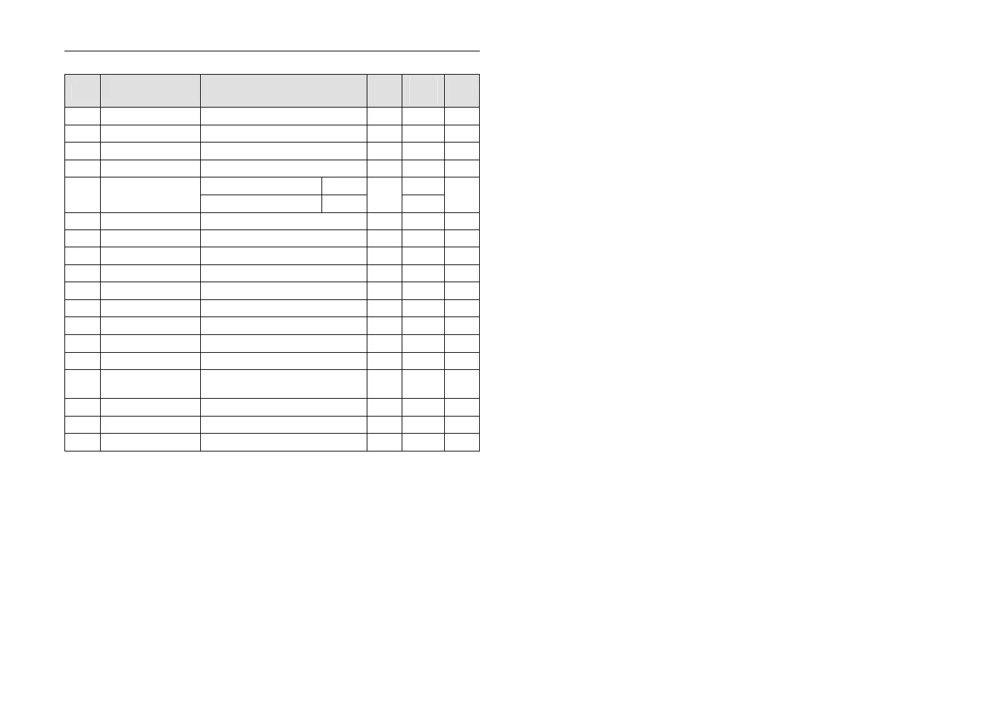
5-2-8. MOT group [MOT]
Ref
LCD keyboard
explanation
Range of set value Unit
setting
Y/N
b00
motor poles 1~8 - 2 N
b01
motor rated cur. y07×(30%~120%) A ★ N
b02
motor rated vol. 100~380 V ★ N
b03
motor rated speed
500~5000 rpm
1500
N
0.00~F13 F03=0
50.00
b04
motor rated
frequency
0.0~F13 F03=0
%
500.0
N
b05
Motor un-load cur.
0~b01 A ★ N
b06
stator resistor 0.000~30.000 ohm
★ N
b07
rotor resistor 0.000~30.000 ohm
★ N
b08
leakage inductance
0.0~3200.0 mH
★ N
b09
mutual inductance
0.0~3200.0 mH
★ N
*b10
reserved - - - -
*b11
reserved - - - -
*b12
reserved - - - -
*b13
reserved - - - -
b14
plus
0.1~2000.0 % 100.0
Y
*b15
reserved - - - -
b16
reserved 0 - 0 N
b17
reserved 0 - 0 N
NOTE:
1) Y/N means the parameter is adjustable or not during running, Y means
it is adjustable, N means it is not.
2) ★ means the parameter’s factory setting is affected by the power and
type. The value refers to the parameters description.
3) *means the function is invalid but reserved.
Section VI. Function Parameter Description
6-1. Basic parameter:
F00: Monitor selection factory setting: 0
The value range is 0~15 monitoring 0~15 different objects under running.
Monitor objects under running
0: Set frequency
Set frequency under frequency setting mode.
1: Actual frequency
Current output frequency.
2: Motor actual current
Detected value of motor’s current.
3: Actual current percentage
Percentage of motor’s actual current and rated current.
4: DC bus voltage
Detected voltage of DC bus.
5: Output voltage
Actual output voltage of inverter.
6: Actual motor speed rpm
During running, the display of the adjusted motor’s actual rotate
speed=60 × Actual output frequency × Rotate speed display plus/Motor
poles
e.g. Actual output frequency50.00Hz, Rotate speed display plus
b14=100.0%, Motor poles b00=2, the display of the adjusted motor’s
actual rotate speed=1500rpm.
During stopping state, checking the motor speed according to residual
stress, renewed speed 500ms.
The display of the adjusted motor’s actual rotate speed=60 × residual
stress frequency × rotate speed display plus/Motor poles
7: Total running time
This parameter indicates the total running time, and the unit is hour or
day.
e.g. If led display value is 10.31, y14 is 0, the actual running time of the
machine is 10 hours,18 minutes and 36 seconds; if led display value is
20.03 and y14 is 1, the actual running time of the machine is 20 days,43
minutes and 12 seconds.
8: IGBT temperature
Detected IGBT temperature inside inverter.
*9~15: Reserved.
 Loading...

