EasyManua.ls Logo

Powtran PI9000 series - User Manual

Powtran PI9000 series
256 pages
Print Icon
To Next Page IconTo Next Page
Loading...
1
Foreword
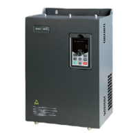
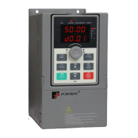
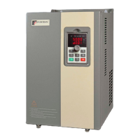
Thank you for choosing POWTRAN PI9000 Series Frequency Inverter. This product
made by POWTRAN is based on years of experience in professional production and
sale, and designed for variety of industrial machinery, fan and water pump drive unit
and IF heavy-duty grinding unit.
This manual provides user the relevant precautions on installation, operational
parameter setting, abnormal diagnosis, routine maintenance and safe use. In order to
ensure correct installation and operation of the frequency converter, please carefully
read this manual before installing it.
For any problem when using this product, please contact your local dealer authorized by
this company or directly contact this company, our professionals are happy to serve you.
The end-users should hold this manual, and keep it well for future maintenance & care,
and other application occasions. For any problem within the warranty period, please fill
out the warranty card and fax it to the our authorized dealer.
The contents of this manual are subject to change without prior notice. To obtain the
latest information, please visit our website.
For more product information, please visit: http:// www.powtran.com
POWTRAN
August, 2014

Table of Contents

Questions and Answers

  • E
    Eric MooreSep 23, 2025
    What does Err.31 mean on Powtran Inverter?
    • T
      Timothy BrightSep 23, 2025
      Err.31 on your Powtran Inverter means that the PID feedback is less than the set value of E2.11. Check the PID feedback signal or set E2.11 to an appropriate value.
  • R
    Ronald ShermanAug 25, 2025
    What causes Err.03 on my Powtran PI9000 and how can I fix it?
    • C
      cheryl81Aug 25, 2025
      Err.03 on your Powtran Inverter can be triggered by a few things. It might be due to a short-circuit or earthing of the inverter output (eliminate peripheral faults). If you're using vector control mode without parameter identification, perform the identification for the motor parameters. Also, check if the deceleration time is too short and increase it if needed. Low voltage can also cause this, so set the voltage to the normal range. Make sure you aren't suddenly increasing the load during deceleration; if you are, cancel the sudden load. Finally, if you haven't installed a braking unit and resistor, do so.
  • N
    Nicole McgeeAug 25, 2025
    What does Err.04 mean on my Powtran PI9000 and how do I resolve it?
    • D
      Devin ProctorAug 26, 2025
      The Err.04 error on your Powtran Inverter can be caused by a short-circuit or earthing of the inverter output, so you should eliminate peripheral faults. Also, if the control mode is vector and without parameter identification, perform the identification for the motor parameters. If the voltage is low, set it to the normal range. Check for sudden load increases during operation and cancel them. Lastly, the inverter might be too small for the job, so choose an inverter with a larger power level if necessary.
  • S
    smossAug 27, 2025
    How to fix Err.05 on a Powtran PI9000 Inverter?
    • J
      John GlassAug 27, 2025
      If your Powtran Inverter is displaying Err.05, here are a few things to check: First, ensure that a braking unit and brake resistor are installed. If the input voltage is too high, adjust it to the normal range. Also, check if there's an external force dragging the motor during acceleration; if so, cancel it or install a braking resistor. Finally, if the acceleration time is too short, increase it.
  • J
    James JarvisAug 27, 2025
    Why is my Powtran PI9000 showing Err.14 and how to fix it?
    • T
      Tiffany SimsAug 27, 2025
      If your Powtran Inverter is showing Err.14, it indicates a problem with overheating. This could be due to a blocked air duct (clean it up), a damaged fan (replace it), a high ambient temperature (decrease it), a damaged module thermistor (replace it), or a damaged inverter module (replace it).
  • N
    Nathan CherrySep 15, 2025
    What does Err.22 mean on Powtran PI9000?
    • C
      Claire ShieldsSep 15, 2025
      Err.22 on your Powtran Inverter indicates overvoltage or overcurrent. Eliminate overvoltage or overcurrent fault.
  • K
    Katherine BakerSep 12, 2025
    What does Err.20 mean on Powtran PI9000?
    • R
      Rachel RiosSep 13, 2025
      Err.20 on your Powtran Inverter can indicate a damaged encoder (replace the encoder), an abnormal PG card (replace the PG card), an encoder model that doesn't match (correctly set the encoder model according to the Actual conditions), or an error in the encoder connection (eliminate the line fault).
  • A
    Alan WhiteSep 14, 2025
    What does Err.21 mean on Powtran PI9000?
    • Y
      ydoyleSep 14, 2025
      Err.21 on your Powtran Inverter indicates a damaged EEPROM chip. Replace the main control panel.
  • J
    jeffreymendozaSep 5, 2025
    What does it mean when my Powtran Inverter shows Err.13?
    • A
      Amanda SmithSep 5, 2025
      If your Powtran Inverter shows Err.13, it could mean that the lead wires from the inverter to the motor are not normal (eliminate peripheral faults), the inverter's three-phase output is unbalanced when the motor is running (check if the motor's three-phase winding is normal and eliminate faults), or the drive panel is abnormal (seek for technical support).
  • M
    Mr. Tyler Santos DDSSep 2, 2025
    Why does my Powtran PI9000 Inverter show Err.11?
    • S
      Shane SanchezSep 2, 2025
      If your Powtran Inverter shows Err.11, it could be due to a few reasons: the power grid voltage is too low (check the power grid voltage), the motor protection parameters (F8.03) are not set appropriately (correctly set this parameter), or the load is too large, or the motor stall occurs (reduce the load and check the motor and its mechanical conditions).

Summary

Foreword

Chapter 1. Inspection and Safety Precautions

1-1. Inspection after unpacking

Steps for checking the inverter after unpacking to ensure all components are present and correct.

1-2. Safety precautions

Outlines crucial safety measures to prevent injury or damage during installation, wiring, and operation.

1-3. Precautions

Lists important precautions related to motor, frequency, mechanical devices, and output side connections.

1-4. Scope of applications

Defines the suitable applications for the inverter and specifies conditions where manufacturer consultation is necessary.

Chapter 2 Standard Specifications

2-1. Technical specifications

Provides detailed technical specifications for various inverter models, including power, voltage, and current ratings.

2-2. Standard specifications

Details general operational specifications, control systems, input/output signals, and protection functions of the inverter.

2-3. Dimensions

Presents the physical dimensions and installation hole sizes for different inverter series and models.

2-3-1. Appearance and installation holes size

Illustrates the physical appearance of the inverter and specifies dimensions for mounting and installation holes.

2-3-2. PI9100 series

Provides dimensional data and installation sizes for the PI9100 series inverters, categorized by power supply level and type.

2-3-3. PI9200 series

Details dimensional specifications and installation sizes for the PI9200 series inverters, covering various base numbers and power ratings.

2-3-4. PI9300 series

Presents the dimensions and installation sizes for the PI9300 series inverters, categorized by power and series.

2-3-5. PI9400 series

Lists the dimensions and installation sizes for the PI9400 series inverters, including various power and series configurations.

2-3-6. Keyboard size diagram

Provides diagrams showing the physical dimensions and mounting hole details for the JP6E9100 and JP6D9200 keyboards.

Chapter 3 Keyboard

3-1. Keyboard description

Describes the operation panel displays of the JP6E9100 and JPR6E9100 keyboard control panels.

3-2. Keyboard Indicators

Explains the function and meaning of the various indicator lights on the inverter's keyboard interface.

3-3. Description of operation panel keys

Details the function of each key on the operation panel, including parameter setting, shifting, and navigation.

3-4. Examples of parameter settings

Provides examples and instructions on how to view and modify function codes and parameters within the inverter's menu structure.

Chapter 4 Commissioning

Commissioning

Outlines the step-by-step process for commissioning the PI9000 inverter, including control manner and parameter setup.

Chapter 5 Function parameter

5-1. Menu grouping

Explains the organization of function parameters into groups (F, E, b, d) and provides a reference guide to their functions and page numbers.

5-1-1. d0 Group - Monitoring function group

Details parameters related to monitoring functions, such as output frequency, voltage, current, and status.

5-1-2. F0 Group - Basic function group

Covers fundamental function parameters including motor control mode, frequency settings, and command sources.

5-1-3. F1 Gruop - Input terminals group

Describes the configuration and function selection for digital and analog input terminals.

5-1-4. F2 Group - Output terminals group

Explains the configuration and function selection for digital and analog output terminals and relays.

5-1-5. F3 Group - Start and stop control group

Details parameters related to starting and stopping the motor, including start-up modes, DC braking, and acceleration/deceleration.

5-1-6. F4 Group - V;F control parameters

Covers parameters specific to V/F control, including V/F curve settings, torque boost, and slip compensation.

5-1-7. F5 Group - Vector control parameters

Details parameters for vector control, including speed loop settings, torque limits, and differential gains.

5-1-8. F6 Group - Keyboard and display

Explains parameters related to the keyboard operation and display functions, including status display and key definitions.

5-1-9. F7 Group - Auxiliary function group

Covers auxiliary functions such as jog operation, jump frequency, and acceleration/deceleration time settings.

5-1-10. F8 Group - Fault and protection

Details various fault types, their possible causes, and corresponding solutions, including protection settings.

5-1-11. F9 Group - Communication parameter

Explains parameters for communication settings, including baud rate, data format, and protocol selection.

5-1-12. FA Group - Torque control parameters

Describes parameters for torque control mode, including setting sources and acceleration/deceleration times.

5-1-13. Fb Group - Control optimization parameters

Covers parameters for optimizing control performance, such as current limiting, voltage settings, and PWM modulation.

5-1-14. FC Group - Extended parameter

Details extended parameters for special applications like proportional linkage and PID start deviation.

5-1-15. E0 Group - Wobbulate, fixed-length and counting

Explains parameters for wobbulate, fixed-length, and counting functions, used in applications like textile winding.

5-1-16. E1 Group - Multi-stage command, simple PLC

Covers parameters for multi-stage command and simple PLC functions, enabling complex sequence control.

5-1-17. E2 Group - PID function

Details parameters for the built-in PID control function, including feedback sources, action direction, and gains.

5-1-18. E3 Group - Virtual DI, Virtual DO

Explains parameters for configuring virtual digital inputs and outputs, allowing flexible signal mapping.

5-1-19. b0 Group - Motor parameters

Covers essential motor parameters that need to be set for accurate inverter control and performance.

5-1-20. y0 Group - Function code management

Provides functions for managing parameters, including initialization, password settings, and display configurations.

5-1-21. y1 Group - Fault query

Details how to query fault history, including fault types, causes, and their corresponding codes.

Chapter 6 EMC (Electromagnetic Compatibility)

6-1. Definition

Defines electromagnetic compatibility in the context of electrical equipment operation.

6-2. EMC standard

Outlines the relevant Chinese and international standards that the inverter complies with regarding EMC.

6-3. EMC directive

Discusses directives related to EMC, including harmonic effects and interference precautions.

Chapter 7 Troubleshooting

7.1 Fault alarm and countermeasures

Lists common fault IDs, failure types, possible causes, and recommended solutions for troubleshooting inverter issues.

Chapter 8 Installation and Spare Circuit

8-1. Operating environment

Specifies the recommended environmental conditions for installing and operating the inverter to ensure optimal performance and longevity.

8-2. Installation direction and space

Provides guidelines on the proper installation direction and required clearance space around the inverter for adequate ventilation.

8-3. Wiring diagram

Illustrates the main circuit and control circuit wiring diagrams for connecting the inverter to power, motor, and control signals.

8-3-1. Wiring diagram(< 11 kW)

Shows the detailed wiring diagram for inverters with power ratings below 11kW, covering main and control circuits.

8-3-2. Wiring diagram(11 kW to 15 kW)

Provides the wiring diagram for inverters with power ratings between 11kW and 15kW, illustrating main and control circuit connections.

8-3-3. Wiring diagram(18.5 kW to 355 kW)

Presents the wiring diagram for inverters with power ratings from 18.5kW to 355kW, detailing main and control circuit connections.

8-4.Main circuit terminal (G type)

Details the main circuit terminal configurations for different power ranges and types of PI9000 inverters.

8-4-1. PI9000 main circuit terminal

Illustrates the physical layout and labeling of main circuit terminals for various PI9000 models.

8-5.Control circuit terminals

Introduces the control circuit terminals and their general categories.

8-5-1. Description of control circuit terminals

Provides a detailed description of each control circuit terminal, including its symbol, name, and function.

8-6.Wiring Precautions:

Lists critical safety precautions and recommendations for wiring the inverter to prevent damage and ensure safe operation.

Chapter 9 Maintenance and Repair

9-1. Inspection and Maintenance

Outlines a routine inspection and maintenance schedule, detailing checks for display, cooling system, body, and circuit terminals.

9-2. Parts for regular replacement

Identifies internal mechanical wear parts that require regular replacement and their standard life times.

9-3. Storage

Provides guidelines for storing the inverter when not in immediate use to maintain its condition.

9-4. Capacitor

Discusses capacitor rebuilding and charging procedures, especially for inverters that have been stored for a long time.

9-5. Measuring and readings

Offers guidance on using instruments for measuring voltage and current, noting potential inaccuracies and limitations.

Chapter 10 Options

10-1. Options

Mentions the availability of optional functional modules like RS485 and PG cards, requiring specific selection during ordering.

10-2. Molded case circuit breaker (MCCB) or earth leakage circuit breaker (ELCB)

Explains the role of MCCB or ELCB as power switches and protective devices for the inverter's power supply.

10-3. AC input reactor

Details the function of AC input reactors in inhibiting harmonics and improving power factor, recommending their use in specific cases.

10-4. Noise filter

Describes the purpose of noise filters in reducing conducted EMI and radio interference, and lists suitable installation environments.

10-5. Contactor

Explains the function of contactors for protection and notes that they should not be used for motor start/stop control.

10-6. Braking unit and braking resistor

Discusses the built-in braking unit for PI9000 series and models requiring external braking units, with tables for matching resistors.

10-7. Output EMI filter

Explains the function of output EMI filters in suppressing noise and leakage current.

10-8. AC output reactor

Describes the use of AC output reactors to inhibit overcurrent and radio interference, especially for long motor cables.

10-9. Input filter

Provides specifications and installation sizes for input filters, differentiating between 380V and 690V models.

10-10. Output filter

Lists specifications and installation sizes for output filters for both 380V and 690V models.

10-11. Input AC choke

Details specifications, including voltage, power, current, and dimensions, for AC input chokes in 380V and 690V configurations.

10-12. Output AC choke

Provides specifications for output AC chokes, listing model, voltage, power, current, and dimensions for 380V and 690V versions.

10-13. DC choke

Lists specifications for DC chokes, including model, voltage, power, current, inductance, and installation size.

10-14. Specifications of circuit breakers, cables and contactors

Provides specifications for circuit breakers, cables, and contactors, including current ratings and dimensions.

Chapter 11 Warranty

1. Warranty terms

Outlines the warranty period and terms, including conditions for return, replacement, and repair services.

2. Exceptions clause

Lists conditions and circumstances under which product quality issues are not covered by the warranty.

3. The following conditions, manufacturers have the right not to be warranty

Specifies conditions where the manufacturer reserves the right to refuse warranty service.

4. In return, replacement, repair service, shall be returned the company, confirmed the attribution of responsibility, can be returned or repair

Describes the procedure for returning, replacing, or repairing products, requiring company confirmation and responsibility attribution.

Appendix I RS485 Communication protocol

I-1 Communication protocol

Defines the serial communication protocol, including transmission information, format, and bus structure for RS485 communication.

I-1-1 Communication content

Details the communication content, including master polling, encoding methods, data transfer, and error checking.

I-1-2 Communications connection

Explains the installation of the RS485 communication module and its connection to control boards.

I-1-3 Definition of communication parameter address

Provides a detailed mapping of communication parameter addresses, explaining labeling rules and examples for accessing inverter settings.

Appendix IV CAN bus communication card use description

IV-1.Overview

Introduces the CAN bus communication card and its suitability for PI9000 inverters, referring to external protocol documents.

IV-2.Mechanical installation and terminal functions

Covers the mechanical installation procedures and describes the terminal functions of the CAN bus communication card.

IV-2-1 Mechanical installation modes:

Illustrates the mechanical installation methods for the CAN bus communication card on different control boards (SCB, LCB).

IV-2-2 Terminal function

Details the terminal functions and specifications for the CAN bus communication card, including signal descriptions.

Appendix V Profibus-DP communication card use description

V-1.Outline

Introduces the Profibus-DP communication card and its purpose for fieldbus control integration with Powtran inverters.

V-2.Terminal function

Describes the terminal functions and configuration options for the Profibus-DP communication card.

V-2-1.DIP switch description

Explains the function of DIP switches for baud rate selection and Profibus-DP communication address settings.

V-2-2.Terminal Function

Details the terminal functions for external communication (J4-6) and PC communication (SW1-8).

V-2-3.LED Indicator Functions

Describes the function and meaning of the LED indicators on the Profibus-DP communication card for status and connection diagnostics.

Warranty Card

1. Warranty terms

Outlines the warranty period and terms, including conditions for return, replacement, and repair services.

2. Exceptions clause

Lists conditions and circumstances under which product quality issues are not covered by the warranty.

3. The following conditions, manufacturers have the right not to be warranty

Specifies conditions where the manufacturer reserves the right to refuse warranty service.

4. In return, replacement, repair service, shall be returned the company, confirmed the attribution of responsibility, can be returned or repair

Describes the procedure for returning, replacing, or repairing products, requiring company confirmation and responsibility attribution.

Customer Feedback Form of Powtran Inverter

Failure

Section for customers to report details about load and control situations, failure types, and descriptions.

Powtran PI9000 series Specifications

General IconGeneral
BrandPowtran
ModelPI9000 series
CategoryInverter
LanguageEnglish

Related product manuals