Chapter 8 Installation and Spare Circuit
195
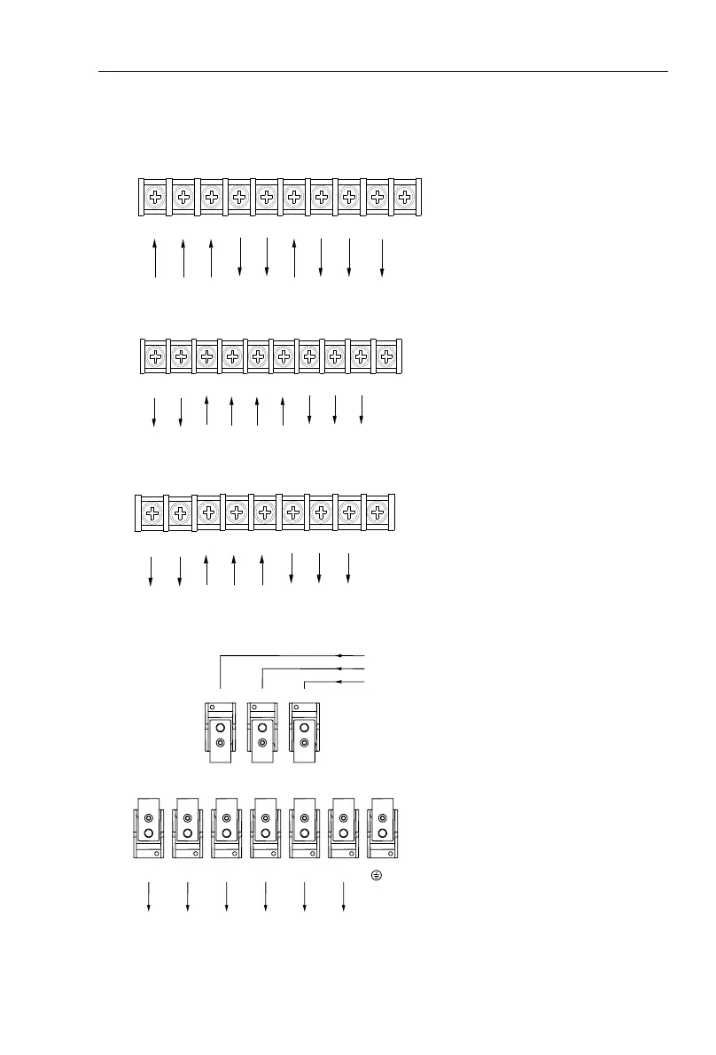
8-4.Main circuit terminal (G type)
8-4-1.PI9000 main circuit terminal
1. Main circuit terminal(<15KW, 380V)
R/L1 S/L2
Braking
resistor
Ground
terminals
RB
U/T1 V/T2
Output end of power
Input end of power
E
P+ P
T/L3
W/T3
DC reactor
2. Main circuit terminal(18.5kW to 160kW, 380V)(Left In, Right Out)
S
T
Input end of
power
Ground
terminals
U/T1 V/T2 W/T3
Output end
of power
E
P-
P+P
R
P/P+:DC reactor
P+/P-:Braking units
3. Main circuit terminal(187kW to 355kW, 380V)(Left In,Right Out)
S
T
Input end of
power
Ground
terminals
U/T1 V/T2 W/T3
Output end
of power
E
P+P
R
P/P+:
DC reactor
4. Main circuit terminal(45kW to 220kW, 380V)(Up In, Down Out)
Note: P/P+ standard configuration is for the shorted state; if external DC reactor is
connected, firstly disconnect and then reconnect.
 Loading...

