Chapter 8 Installation and Spare Circuit
196
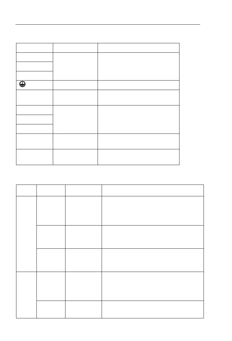
8-4-2.Function description of main circuit terminal
Connect to three-phase power
supply, single-phase connects to R,
T
Braking resistor
terminals
Connect to braking resistor
Connect to three-phase motor
Connect to DC reactor(remove the
shorting block)
8-5.Control circuit terminals
8-5-1. Description of control circuit terminals
External+
10V power
supply
Output +10V power supply, maximum output
current: 10mA
Generally it is used as power supply of
external potentiometer, potentiometer
resistance range: 1kΩ to 5kΩ
External+24V
power supply
Output +24V power supply, generally it is
used as power supply of digital input and
output terminals and external sensor.
Maximum output current: 200mA
External
power input
terminal
When external signal is used to drive, please
unplug J5 jumpers ,
PLC
must be connected
to external power supply, and to +24V
(default).
1.Input range:(DC 0V to 10V/0 to 20mA),
depends on the selected J3 jumper on control
panel.
2.Input impedance: 20kΩ with voltage input,
510Ω with current input.
1.Input range:(DC 0V to 10V/0 to 20mA),
depends on the selected J4 jumper on control
panel.
 Loading...

