Chapter 8 Installation and Spare Circuit
198
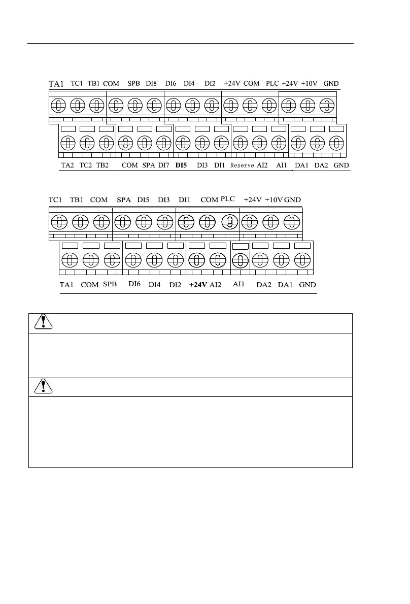
8-5-2.Arrangement of control circuit terminals
1. 9KLCB board control circuit terminals
2. 9KSCB board control circuit terminals
8-6.Wiring Precautions:
Make sure that the power switch is in the OFF state before wiring operation, or electrical shock may
occur!
Wiring must be performed by a professional trained personnel, or this may cause damage to the
equipment and personal injury!
Must be grounded firmly, otherwise there is a danger of electric shock or fire hazard !
Make sure that the input power is consistent with the rated value of inverter, otherwise which may
cause damage to the inverter!
Make sure that the motor matches the inverter, otherwise which may cause damage to the motor or
activate the inverter protection!
Do not connect power supply to U/T1, V/T2, W/T3 terminals, otherwise which may cause damage to
the inverter!
Do not directly connect braking resistor to DC bus (P), (P +) terminals, otherwise which may cause a
fire!
※ The U, V, W output end of inverter can not install phase advancing capacitor or
RC absorbing device. The inverter input power must be cut off when replacing the
motor
※ Do not let metal chips or wire ends into inside the inverter when wiring, otherwise
which may cause malfunction to the inverter.
※ Disconnect motor or switch power-frequency power supply only when the inverter
stops output
 Loading...

