Chapter 8 Installation and Spare Circuit
197
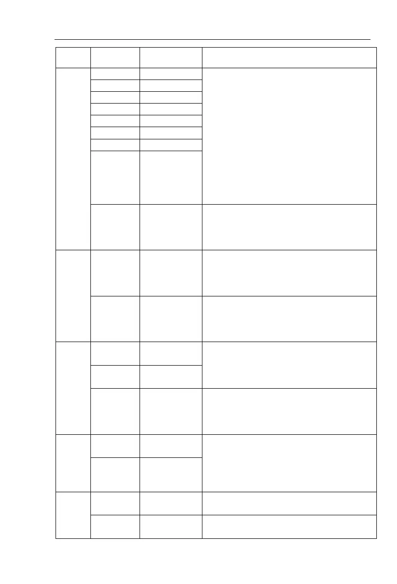
2.Input impedance: 20kΩ with voltage input,
510Ω with current input.
1.Opto-coupler isolation, compatible with
bipolar input
2.Input impedance: 4.7kΩ
3.Voltage range with level input: 9V to 30V
4
. Below 11KW: (DI1 to DI6)drive manner is
controlled by J5, when external power supply
is used to drive, please unplug J5 jumpers ,
5
. Above 11KW: (DI1 to DI4)drive manner is
controlled by J6, (DI5 to DI8)drive
manner is controlled by J5, when external
power supply is used to drive, please
unplug J5 jumpers ,
High-speed
pulse input
terminals
Except the function of DI1 to DI4,DI6 to
DI8,DI5 can also be used as high-speed pulse
input channels.Maximum input frequency:
100kHz
The selected J2 jumper on control panel
determines voltage or current output. Output
voltage range: 0V to 10V , output current
range: 0mA to 20mA
The selected J1 jumper on control panel
determines voltage or current output. Output
voltage range: 0V to 10V , output current
range: 0mA to 20mA
Opto-coupler isolation, bipolar open collector
output
Output voltage range: 0V to 24V , output
current range: 0mA to 50mA
Subject to function code(F2.00)"SPB terminal
output mode selection"
As a high-speed pulse output, the highest
frequency up to 100kHz;
Contactor drive capacity: normally closed
contact 5A/AC 250V,normally open contact
3 A/AC 250V,1A/ DC 30V, COSø = 0.4.
Normally
closed
terminals
 Loading...

