Section II. Installation & Standby Circuit
2-3. Wiring
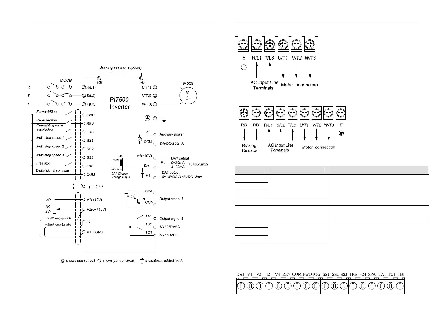
The wiring of frequency inverter includes two parts: main circuit and control
circuit. The user must ensure correct connections according to the following
connection diagram.
2-4. Main Circuit Terminals:
2-4-1. PI7500 Main Circuit Terminals
Section II. Installation & Standby Circuit
(1)0.4~0.75KW G1
(2) Other types of PI7500
2-4-2. Terminal Function
Terminal
Description Functions
R/L1
S/L2
T/L3
Power input for
frequency inverter
Connected to 3-phase power
(Single input connected to R ,T)
E/PE Grounding point Grounded to the earth
RB, RB′
Connection point for
braking resistance
U/T1
V/T2
W/T3
3 Phase Output Connected to 3-phase motor
2-5. Control Circuit Terminals
2-5-1 Control Circuit Terminals distribution.
 Loading...

