21
DESCRIPTIONS
INPUT-1 : Dry-Bulb RTD Pt100, 3-Wire (Terminals 1, 2 and 3)
Connect single leaded end of RTD bulb to terminal 1 and the double leaded ends to terminal 2 and 3
(interchangeable) as shown in Figure 12.2 (a). Use copper conductor leads of very low resistance
for RTD connections. Ensure that all 3 leads are of the same gauge and length. Use single run
cables avoiding any intermediate joints.
Figure 12.2 (a)
3
2
1
OUTPUT-1 (HEATING) & OUTPUT-2 (HUMIDIFICATION)
The Output-1 and Output-2 are configured for DC Voltage capable of switching the external SSR (Solid State Relay) or Relay.
Use Zero-Crossover, 3 to 30 VDC operated SSR, rated approximately 1.5 times the actual load rating. In case of relay, use
Relay with coil rated for 5VDC. The terminals for output-1 & output-2 are as shown in Figure 12.3.
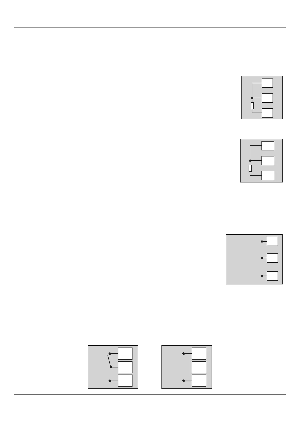
INPUT-2 : Wet-Bulb RTD Pt100, 3-Wire (Terminals 16, 17 and 18)
HEATING (Terminals 4 & 6)
Connect terminals 6 & 4 to SSR (+) & (-) respectively OR to the relay coil.
HUMIDIFICATION (Terminals 5 & 6)
Connect terminals 6 & 5 to SSR (+) & (-) respectively OR to the relay coil.
Figure 12.3
6
5
4
5VDC Voltage for
SSR / Relay coils
Open Collector (OC2)
for SSR-2/Relay-2
(Humidification)
Open Collector (OC1)
for SSR-1/Relay-1
(Heating)
OUTPUT- 3 (Terminals 7,8 and 9)
The Output-3 module (if fitted) can be configured as either Relay or SSR Drive for Alarm or Compressor Control output. The
configuration is through hardware jumper settings on the module as described in Section 8: Hardware Assembly And
Configurations.
The terminals for Relay, DC Voltage pulses output for SSR output are shown in Figure 12.4 (a) & 12.4 (b), respectively.
Figure 12.2 (b)
18
17
16
Connect single leaded end of RTD bulb to terminal 16 and the double leaded ends to terminal 17
and 18 (interchangeable) as shown in Figure 12.2 (b). Use copper conductor leads of very low
resistance for RTD connections. Ensure that all 3 leads are of the same gauge and length. Use
single run cables avoiding any intermediate joints.
Figure 12.4 (a)
9
8
7
N/O
C
N/C
Figure 12.4 (b)
9
8
7
+
_
User Manual
HumiTherm-c (Dry-Wet)
 Loading...