39
HARDWARE ASSEMBLY & CONFIGURATIONS
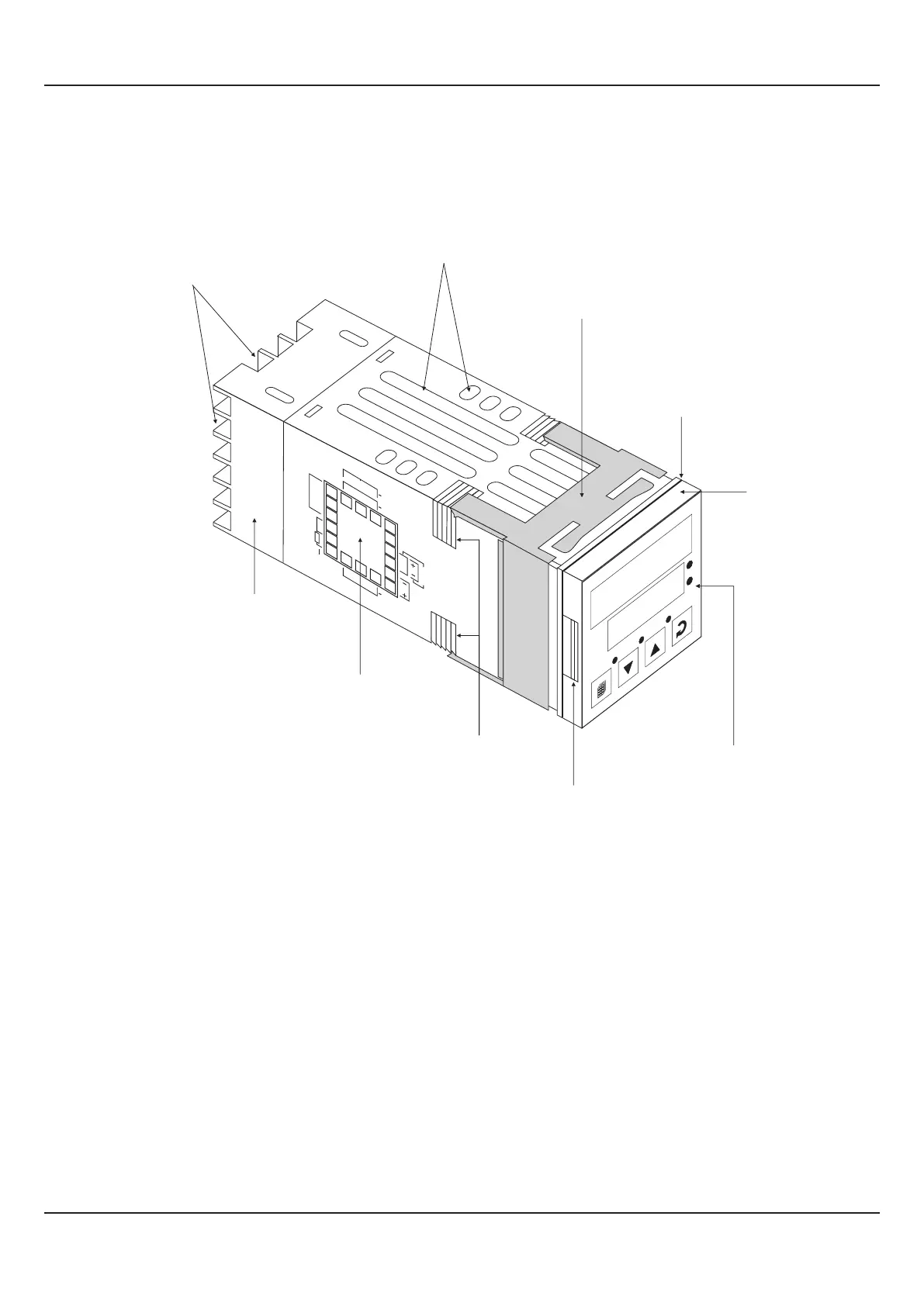
OUTER CASE
The Figure 10.1 above shows the controller outer-case when viewed with controller front label upright. The controller outer
case is a rigid plastic Enclosure into which the electronics assembly fits. The Enclosure in turn fits into the standard DIN size
panel cutout, as described in Section 11 : Mechanical Installation.
Notice the nomenclatures used to identify the various parts as the same are used throughout the sections describing
installation, configuration and electrical connections.
Figure 10.1
UP
UP
Front Label
Pullout Grip
Enclosure
Connection Diagram
Rear Terminals
Ventilations
Ratchets
Panel Mounting Clamp
Panel Sealing
Gasket
Bezel
PPI
HumiTherm-c
AL1
TUN
AL2
1
2
%RH
°C
HumiTherm
1
2
3
4
5
6
7
8
9
10
1
1
12
13
14
15
16
17
18
+5V
OC2
OC1
OUTPUT 1 & 2
Pt100
IN P U T 1
O
U
TP
U
T
3
+
R
H
S
E
NS
O
R
SERIAL
COMMS.
+
SSR
RELAY
N/O
N/C
C
PPI
L
N
A
C
DC
SUPPLY
-
Ex
IN
P
U
T
2
_
ELECTRONIC ASSEMBLY
The electronic assembly can be removed from the plastic Enclosure and placed back as described below and illustrated in
Figure 10.2
Removal
1. Hold the controller with its front label upright.
2. Hold the Bezel with the fingers on the pullout grips provided on the left and right sides of the bezel. Pull the bezel outward.
The assembly comes out with the bezel.
User Manual
HumiTherm-c (Temp+RH)
Section 10
 Loading...