40
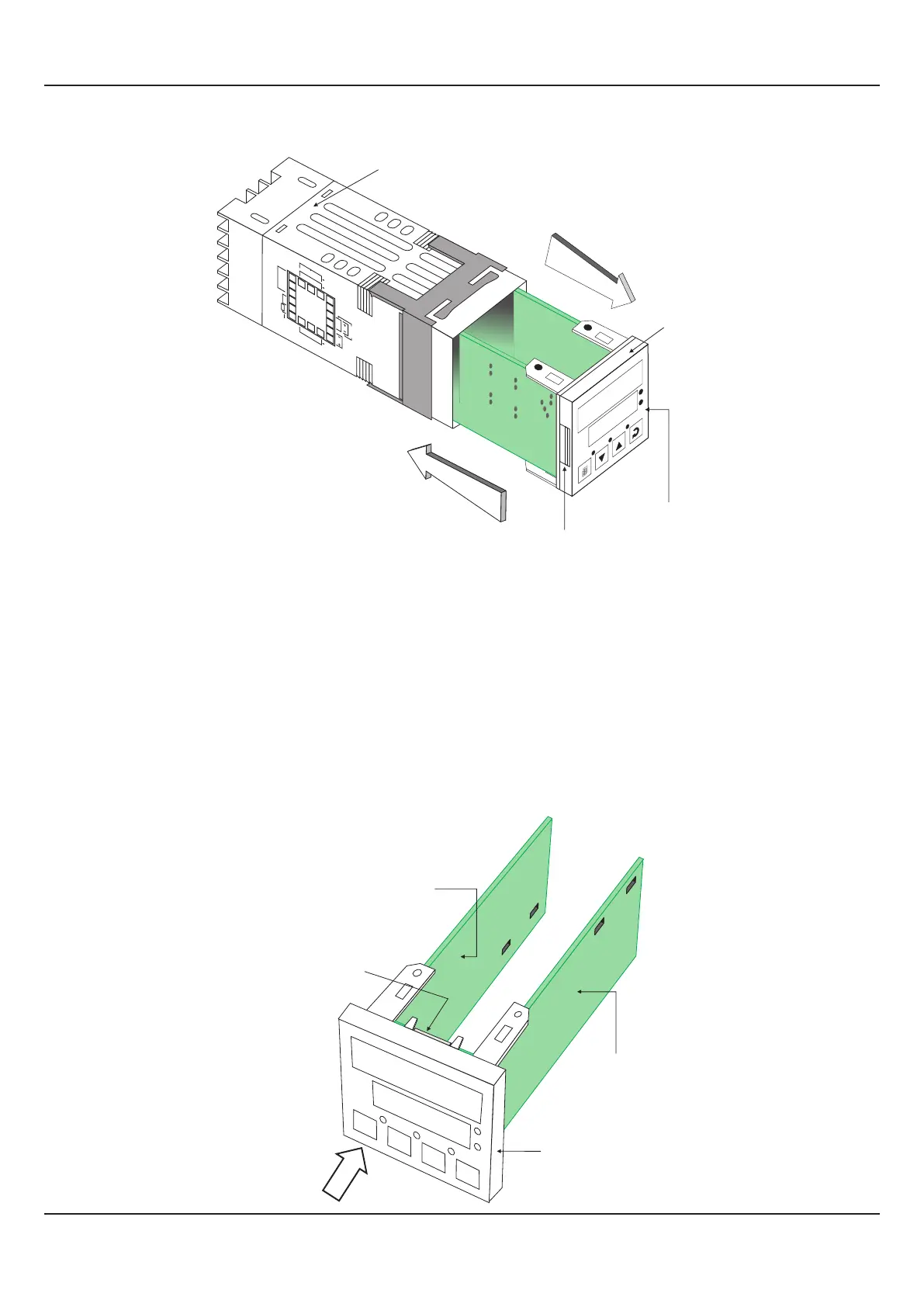
Figure 10.2.
‘UP’ inscribed on topside
UP
UP
Placing Back
Removal
Pullout Grip
Bezel
Front Label
PPI
HumiTherm-c
AL1
TUN
AL2
1
2
%RH
°C
HumiTherm
1
2
3
4
5
6
7
8
9
10
11
12
13
14
15
16
17
18
+5V
OC2
OC1
OUTPUT 1 & 2
Pt100
IN PU T 1
O
UT
P
UT 3
+
R
H
S
E
NS
OR
SERIAL
COMMS.
+
SSR
RELA
Y
N/O
N/C
C
PPI
L
N
A
C
DC
SUPPLY
-
Ex
IN P
U
T 2
_
Placing Back
1. Hold the bezel with the front label upright.
2. Hold the Enclosure such that the UP inscribed on the Enclosure is on the topside. Insert the bezel gently with the boards on
either side sliding into the guides provided inside of the Enclosure.
3. Ensure that the bezel fits in tight on the Enclosure-front to secure the panel-sealing gasket.
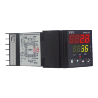
The Figure 10.3 below shows the basic electronics assembly of the controller (without plug-in modules). The basic electronics
assembly comprises of 3 Printed Circuit Boards. As shown in the figure, when viewed from the front, the CPU board is to the
right, Power-supply board is to the left and the Display board is behind the bezel.
Figure 10.3
VIEW
PPI
Power Supply Board
CPU Board
Display Board
Bezel
HumiTherm-c
User Manual
HumiTherm-c (Temp+RH)
 Loading...