68 69
5350QE01.doc 2005-03-16 Rev. AC 3/7
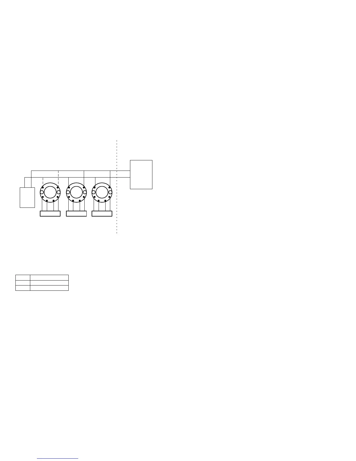
SENSOR
32V
Class 2
Power Supply
Unclassified LocationHazardous (Classified) Location
5350A
1
2
3
45
6
Class I, Division2, Groups, A,B,C,D
OR
Class I, Zone 2, IIC
SENSOR
Approved
Termi-
nation
SENSOR
5350A 5350A
This device must not be
connected to any
associated apparatus
which uses or generates
more than 250 VRMS
Terminal 3, 4, 5, 6
Vt or Uo : 5.71 V
It or Io : 8.4 mA
Pt or Po : 12 mW
Ca or Co : 40
F
La or Lo : 200 mH
Terminal 1.2
Ci: 2.0 nF
Li: 1
H
T1..T4
-40
C
Ta
+85
C
T5
-40
C
Ta
+75
C
T6
-40
C
Ta
+60
C
See installation notes:
5350QE01.doc 2005-03-16 Rev. AC 4/7
Installation notes:
FM / UL / CSA:
For installation in the US the 5350 shall be installed according to the National Electrical
Code (ANSI-NFPA 70).
For installation in Canada the transmitter shall be installed in a suitable enclosure to meet
installation codes stipulated in the Canadian Electrical Code (CEC).
The entity concept:
Equipment that is FM / UL / CSA-approved for intrinsic safety may be connected to barriers
based on the ENTITY CONCEPT. This concept permits interconnection of approved
transmitters, meters and other devices in combinations which have not been specifically
examined by FM / UL / CSA, provided that the agency's criteria are met. The combination is
intrinsically safe, if the entity concept is acceptable to the authority having jurisdiction over
the installation.
The entity concept criteria are as follows:
The intrinsically safe devices, other than barriers, must not be a source of power.
The maximum voltage Ui (V
MAX
) and current Ii (I
MAX
), and maximum power Pi (Pmax), which
the device can receive and remain intrinsically safe, must be equal to or greater than the
voltage (Uo or V
OC
or V
t
) and current (Io or I
SC
or I
t
) and the power Po which can be delivered
by the barrier.
The sum of the maximum unprotected capacitance (C
i
) for each intrinsically device and the
interconnecting wiring must be less than the capacitance (C
a
) which can be safely
connected to the barrier.
The sum of the maximum unprotected inductance (L
i
) for each intrinsically device and the
interconnecting wiring must be less than the inductance (L
a
) which can be safely connected
to the barrier.
The entity parameters Uo,V
OC
or V
t
and Io,I
SC
or I
t
, and C
a
and L
a
for barriers are provided by
the barrier manufacturer.
FISCO/FNICO rules:
The FISCO Concept allows the interconnection of intrinsically safe apparatus to associated
apparatus not specifically examined in such combination. The criterion for such
interconnection is that the voltage (Vmax), the current (Imax) and the power (Pi) which
intrinsically safe apparatus can receive and remain intrinsically safe, considering faults, must
be equal or greater than the voltage (Uo, Voc, Vt), the current (Io, Isc, It,) and the power
(Po) which can be provided by the associated apparatus (supply unit). In addition, the
maximum unprotected residual capacitance (Ci) and inductance (Li) of each apparatus (other
than the terminators) connected to the Fieldbus must be less than or equal to:
FISCO: 5 nF and 10
H.
FNICO: 5 nF and 20
H
 Loading...