EasyManua.ls Logo

PR electronics 5111 User Manual

PR electronics 5111
59 pages
Go to English
To Next Page IconTo Next Page
Page #1 background imageLoading...
Page #1 background image
Galvanic isolators for analogue and digital
signals as well as HART
®
signals. A wide product range
with both loop-powered and universal isolators featuring
linearisation, inversion, and scaling of output signals.
Programmable displays with a wide se-
lection of inputs and outputs for display of temperature,
volume, weight, etc. Feature linearisation, scaling, and
difference measurement functions for programming via
PReset software.
Interfaces for analogue and digital signals
as well as HART
®
signals between sensors / I/P convert-
ers / frequency signals and control systems in Ex zone 0,
1 & 2. Feature options such as mathematical functions
and 2 wire transmitter interfaces.
Flexible motherboard solutions for sys-
tem 5000 modules. Our backplane range features fl exible
8 and 16 module solutions with confi guration via PReplan
8470 – a PC program with drop-down menus.
A wide selection of transmitters for DIN
form B mounting and DIN rail modules with analogue
and digital bus communication ranging from application-
specifi c to universal transmitters.
Isolation
Temperature
Ex barriers
Displays
Backplane
DK
UK
FR
DE
Side 1
Page 29
Page 57
Seite 85
SIGNALS THE BEST
5111
Universal
Transmitter
No. 5111V106-IN (0606)
From ser. no. 040020801

Table of Contents

Question and Answer IconNeed help?

Do you have a question about the PR electronics 5111 and is the answer not in the manual?

PR electronics 5111 Specifications

General IconGeneral
Supply voltage, nom.24 V DC
Supply voltage, max.30 V DC
Accuracy± 0.1 % of full scale
Protection ClassIP 20
Dimensions22.5 x 100 x 115 mm
Signal / noise ratio≥ 60 dB
EMC immunityEN 61326
Input signalRTD, Thermocouple, Resistance, mA, V
Output signal4-20 mA
Output4-20 mA
Operating Temperature-20 to +60 °C

Summary

SAFETY INSTRUCTIONS

UNIVERSAL TRANSMITTER 5111 FEATURES

Key Features

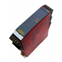
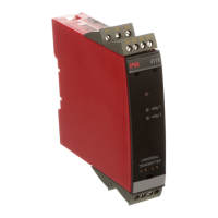
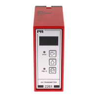
Highlights programmability, isolation, ATEX certification, and DIN rail mounting.

INPUT TYPES

Thermocouple (TC) and RTD Inputs

Overview of TC and RTD input capabilities and compensation.

OTHER INPUT TYPES

Resistance, Current, and Voltage Inputs

Details on resistance, current, and voltage input specifications.

ELECTRICAL SPECIFICATIONS

Common Specifications

General electrical parameters like supply voltage, consumption, and fuse.

INPUT SPECIFICATIONS DETAILS

TC, RTD, and Resistance Input Specs

Detailed specifications for TC, RTD, and resistance inputs.

Voltage and Bridge Input Specs

Detailed specifications for voltage and bridge inputs.

CURRENT INPUT SPECIFICATIONS

OUTPUT SPECIFICATIONS

Current, Voltage, and Relay Outputs

Details on current, voltage, and relay output capabilities.

ORDERING AND MECHANICAL INFO

Mechanical Specifications

Physical dimensions and mounting information.

BLOCK DIAGRAM

TERMINAL PLACEMENT

HARDWARE PROGRAMMING

WIRING DIAGRAMS AND LED INDICATION

Wiring Diagrams

General mention of wiring diagrams availability.

ERROR FUNCTIONS

WIRING DIAGRAMS FOR RTD AND RESISTANCE INPUT

WIRING DIAGRAMS FOR THERMOCOUPLE INPUT

WIRING DIAGRAMS FOR DC VOLTAGE INPUT

WIRING DIAGRAMS FOR DC CURRENT INPUT

WIRING DIAGRAMS FOR DC BRIDGE INPUT (E.G. LOAD CELLS)

Related product manuals