45
WIRING DIAGRAMS
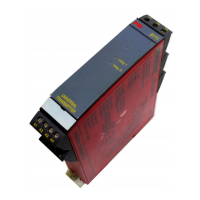
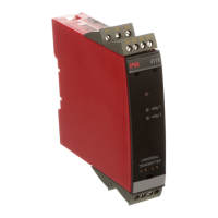
PRetrans 5111 is a universal transmitter configured with input and output para-
meters according to your order.
A printout of the configuration from factory is placed inside each PRetrans 5111.
By means of the PReset programme incl. Opto Link type 5901 and a PC you can
configure PRetrans 5111 yourself.
You will find a detailed description in the PReset manual.
The PRetrans 5111 manual contains wiring diagrams, grouped according to input
types. PRetrans 5111 is available in standard and ATEX EEx version as follows:
5111-1- without trip amplifiers and
5111-2- with 2 trip amplifiers.
LED INDICATION
The green LED is flashing during normal operation. The LED is off when commu-
nicating to or from the PRetrans 5111. The yellow LED is on when the relay is
active.
HARDWARE PROGRAMMING:
DP2: Auxiliary voltage SW ON SW OFF
Loop supply 2 1
8 V excitation 1 2
2.5 V ref. - 1, 2
DP1: Analogue output SW ON SW OFF
Output ±20 mA 4 1, 2, 3
Output ±10 VDC 1, 3, 4 2
Output ±1 VDC 1, 2, 3 4
44
In PRetrans 5111 the input terminals are situated on the bottom of the transmit-
ter. Output and supply terminals are situated on the top of the transmitter.
TERMINAL PLACEMENT: