49
D
A
RE 1
RE 2
24
23
22
21
12
11
32
31
DP 1
PR 5111
.
5
supply
analogue output -
analogue output +
relay 1
relay 1
relay 2
relay 2
supply
24...230 VAC /
24...250 VDC
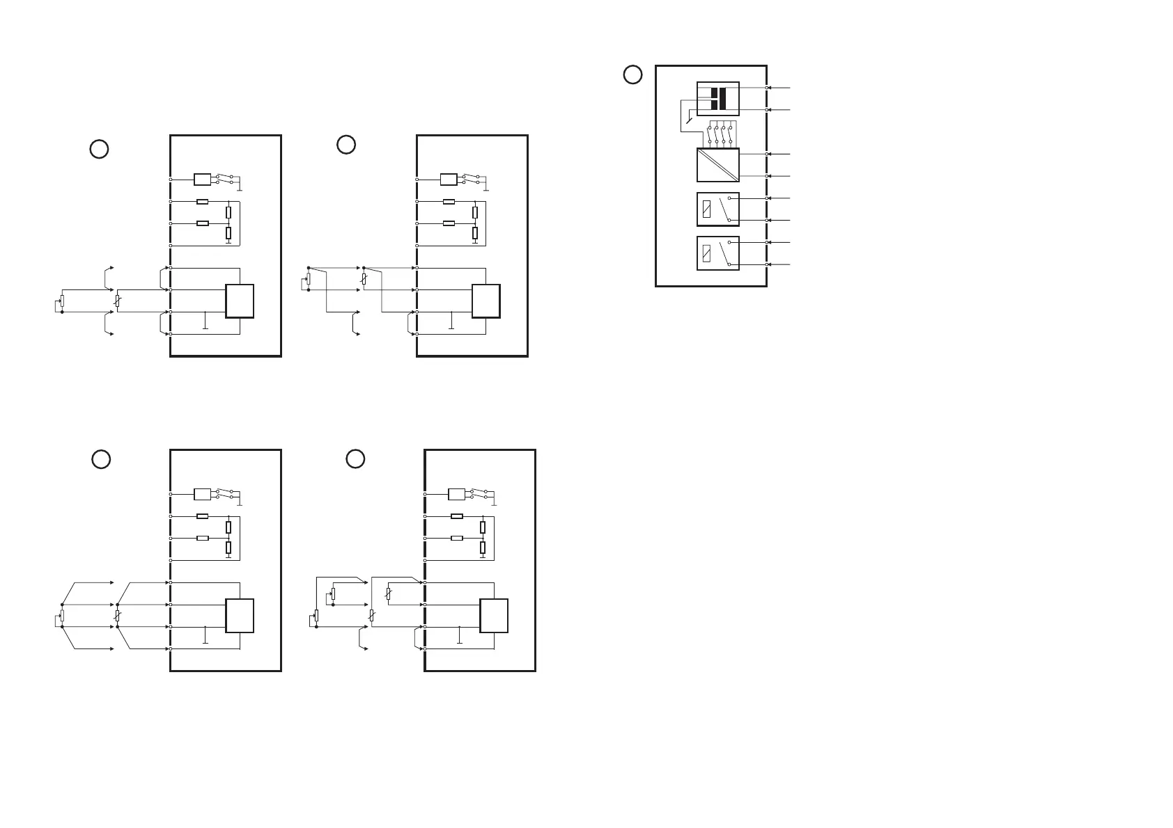
Wiring of power supply, analogue out-
put, and relay outputs.
48
WIRING DIAGRAMS
FOR RTD AND RESISTANCE INPUT
MUX
10
50 k
PTC
5 M
41
42
43
44
51
52
53
54
DP2,1
DP2,2
Ω
Ω
Ω
Vreg
PR 5111
1
Potmeter RTD
MUX
10
50 k
PTC
5 M
41
42
43
44
51
52
53
54
DP2,1
DP2,2
Ω
Ω
Ω
Vreg
PR 5111
.
2
Potmeter RTD
2-wire input for RTD temperature
sensor and variable resistance
(potentiometer).
3-wire input for RTD temperature
sensor and variable resistance
(potentiometer).
MUX
10
50 k
PTC
5 M
41
42
43
44
51
52
53
54
DP2,1
DP2,2
Ω
Ω
Ω
Potmeter RTD
Vreg
PR 5111
3
MUX
10
50 k
PTC
5 M
41
42
43
44
51
52
53
54
DP2,1
DP2,2
Ω
Ω
Ω
Vreg
PR 5111
4
hot
cold
high
low
4-wire input for RTD temperature
sensor and variable resistance
(potentiometer).
Differential input for RTD temperature
sensor and variable resistances
(potentiometers).