37
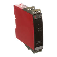
STATUS INDICATION:
A green LED in the enclosure front indicates by flashing light that the transmitter
is operating correctly.
By activation of the calibration button behind the front cover the green LED lights
constantly.
A yellow LED is ON for each active output relay.
ELECTRICAL SPECIFICATIONS - TYPE 5111:
Specifications range:
-20°C to +60°C
Common specifications:
Supply voltage ........................................... 21.6...253 VAC
19.2...300 VDC
Frequency ................................................... 50...60 Hz
Internal consumption ................................. 2.5 W
Max. consumption ..................................... 3 W
Fuse ............................................................ 400 mA SB / 250 VAC
Isolation, test / operation ........................... 3.75 kVAC / 250 VAC
Communications interface ......................... Opto Link 5901
Signal / noise ratio ..................................... Min. 60 dB
Signal dynamics, input ............................... 23 bit
Signal dynamics, output ............................ 16 bit
Response time (programmable)
Min. ........................................................ Updating time x 2.5
Max. ....................................................... 250 s
Calibration temperature ............................. 20...28°C
Temperature coefficient .............................. < ±0.01% of span/°C
Linearity error ............................................. < 0.1% of span
Effect of supply voltage change ................ < 0.001% of span/%V
Auxiliary voltages:
Loop supply ............................................... 16 VDC / 20 mA
Reference voltage ...................................... 2.5 VDC ±0.5% / 15 mA
Excitation supply ........................................ 8.0 VDC ±0.5% / 25 mA
EMC immunity influence ............................ < ±0.5%
Wire square (max.) ..................................... 1 x 2.5 mm
2
stranded wire
Screw terminal torsion ............................... 0.5 Nm
Relative air humidity ................................... < 95% RH (non-cond.)
Dimensions (HxWxD) .................................. 109 x 23.5 x 130 mm
DIN rail type ................................................ DIN 46277
By 2-wire sensor connection it is possible to compensate cable resistance with a
calibration button directly from the front cover. Sensor error detection available.
Resistance input in ranges with 16 bit resolution for resistance measurement.
Max. range 5 kΩ. Cable compensation by 3- or 4-wire connection. 0% and 100%
process calibration is possible with the calibration button directly from the front
cover.
Cable breakage detection available.
Current input in ranges with a 15 bit bipolar resolution for DC current signals.
0% and 100% process calibration is possible with the calibration button directly
from the front cover.
Cable breakage detection available on 4...20 mA signals.
Voltage input in ranges with a 15 bit bipolar resolution for DC voltage signals, 3-
wire potentiometer, load cells, pressure transducers, etc. 0% and 100% process
calibration is possible with the calibration button directly from the front cover.
AUXILIARY SUPPLIES:
(Selected by internal DIP-switches).
Loop supply 16 VDC / 20 mA for supply of 2-wire transmitter.
Reference voltage 2.5 VDC, 15 mA as reference for 3-wire potentiometers e.g.
as a position indicator from analogue valves etc.
Excitation voltage 8 VDC, 25 mA for supply of load cells, pressure transducers,
etc.
OUTPUTS:
(Selected by internal DIP-switches).
Current output with 13 bit bipolar resolution programmable in the range ±20 mA.
Maximum offset is 75% of max. output value.
Voltage output with 13 bit bipolar resolution in the ranges ±1 VDC and ±10 VDC.
Max. load 20 mA.
Maximum offset is 75% of max. output value.
Relay output (relay 1 and 2) is selected as a make or break function. The relays
can be used as trip amplifier or / and sensor error alarm for a TC, an RTD, a
resistance input and current input.
36
 Loading...