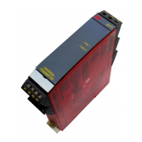
55
WIRING DIAGRAMS
FOR DC BRIDGE INPUT (E.G. LOAD CELLS)
MUX
10
50 k
PTC
5 M
41
42
43
44
51
52
53
54
DP2,1
DP2,2
Ω
Ω
Ω
Vreg
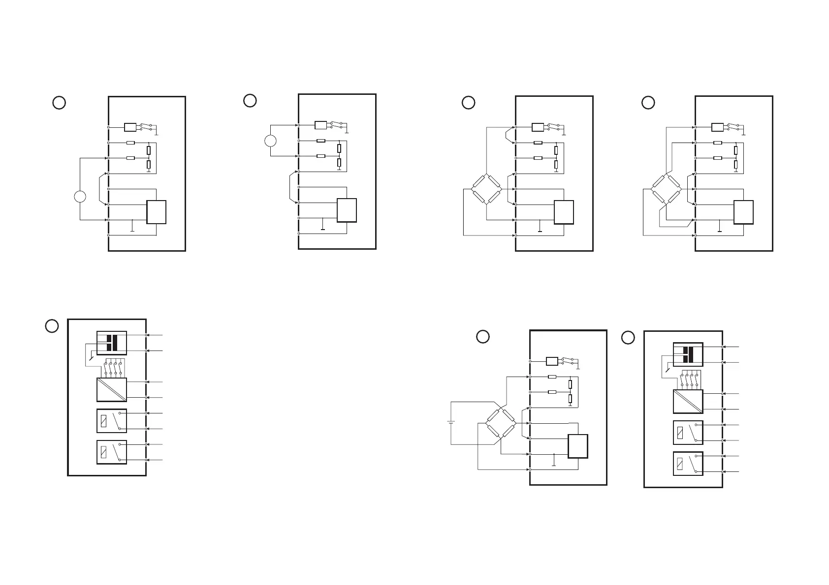
PR 5111
1
V
out. +
out.-
V
exc. -
V
exc. +
MUX
10
50 k
PTC
5 M
41
42
43
44
51
52
53
54
DP2,1
DP2,2
Ω
Ω
Ω
Vreg
PR 5111
2
V
out. +
out.-
V
exc. -
V
exc. +
4-wire bridge input with internal
excitation voltage. DP2 is set to
8 V excitation.
±5 mV ≤ span ≤ ±70 mV.
6-wire bridge input with internal
excitation voltage. DP2 is set to
8 V excitation.
±5 mV ≤ span ≤ ±70 mV.
MUX
10
50 k
PTC
5 M
41
42
43
44
51
52
53
54
DP2,1
DP2,2
Ω
Ω
Ω
Vreg
PR 5111
+
-
3
V
out. +
V
out. -
V
exc. -
V
exc. +
Max. 8 VDC
6-wire bridge input with external
excitation voltage. (Max. 8 VDC).
±5 mV ≤ span ≤ ±70 mV.
D
A
RE 1
RE 2
24
23
22
21
12
11
32
31
DP 1
PR 5111
.
4
supply
analogue output -
analogue output +
relay 1
relay 1
relay 2
relay 2
supply
24...230 VAC /
24...250 VDC
Wiring of power supply, analogue
output, and relay outputs.
54
WIRING DIAGRAMS
FOR DC CURRENT INPUT
A
-
+
MUX
10
50 k
PTC
5 M
41
42
43
44
51
52
53
54
DP2,1
DP2,2
Ω
Ω
Ω
Vreg
PR 5111
1
Bipolar current input for
±2 mA ≤ span ≤ ±100 mA.
T
+
-
MUX
10
50 k
PTC
5 M
41
42
43
44
51
52
53
54
DP2,1
DP2,2
Ω
Ω
Ω
Vreg
PR 5111
2
2-wire
transmitter
D
A
RE 1
RE 2
24
23
22
21
12
11
32
31
DP 1
PR 5111
.
3
supply
analogue output -
analogue output +
relay 1
relay 1
relay 2
relay 2
supply
24...230 VAC /
24...250 VDC
Wiring of power supply, analogue output,
and relay outputs.
2-wire transmitter input with loop
supply.
(DP 2) is set to loop supply.
2 mA ≤ span ≤ 20 mA.