Current outout:
Signal range (span) ...................................... 0...20 mA
Programmable signal ranges ...................... 0...20 / 4...20 /
20...0 / 20...4 mA
Load (max.) .................................................. 20 mA / 800 Ω / 16 VDC
Load stability ............................................... ≤ 0.01% of span / 100 Ω
Sensor error detection ................................ 0 / 3.5 / 23 mA / none
NAMUR NE 43 Upscale .............................. 23 mA
NAMUR NE 43 Downscale .......................... 3.5 mA
Current limit ................................................. ≤ 28 mA
Relay outputs:
Hysteresis, min ............................................ 0.1°C / °F or 0.1% of span / 1 count
Hysteresis, max ........................................... 25% of span
Max. voltage ................................................ 250 VRMS
Max. current ................................................ 2 A / AC
Max. AC power ........................................... 500 VA
Max. current at 24 VDC .............................. 1 A
Sensor error detection ................................ Make / Break / Hold / None
UL installation requirement:
For use on a flat surface of a Type 1 enclosure
Use 60/75°C cobber conducters only
Max. ambient temperature .......................... 60°C
Max. wire size, pins 41...46 ......................... AWG 30-16
Max. wire size, others ................................. AWG 30-12
UL file number ............................................. E248256
Marine approval:
Det Norske Veritas, Ships & Offshore ......... Standard for Certification No. 2.4
Observed authority requirements: Standard:
EMC 2004/108/EC
Emission and immunity ......................... EN 61326
LVD 73/23/EEC ............................................ EN 61010-1
UL, Standard for Safety .............................. UL 508
Sensor error detection / sensor error detection outside range:
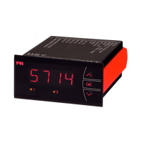
Sensor error check in 5714 variants
Variant: Configuration Sensor error detection:
5714A Always: ON
5714B
ERR1=NONE, ERR2=NONE: OFF
else: ON
5714C
O.ERR=NONE: OFF
else: ON
5714D
ERR1=NONE, ERR2=NONE, O.ERR=NONE: OFF
else: ON
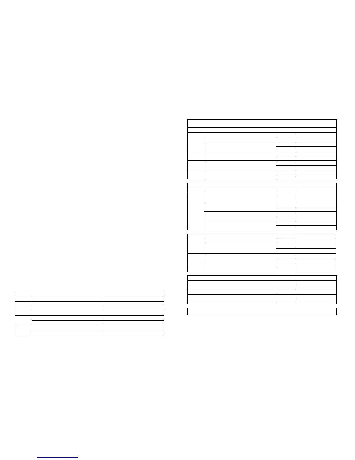
Outside range readout (IN.LO, IN.HI):
If the valid range of the A/D converter or the polynomial is exceeded
Input Range Readout Limit
VOLT
0..1 V / 0.2..1 V
IN.LO < -25 mV
IN.HI > 1.2 V
0..10 V / 2..10 V
IN.LO < -25 mV
IN.HI > 12 V
CURR 0..20 mA / 4..20 mA
IN.LO < -1.05 mA
IN.HI > 25.05 mA
POTM -
IN.LO < -0.5%
IN.HI > 100.5%
TEMP TC / Pt100
IN.LO < temperature range
IN.HI > temperature range
Sensor error detection (SE.BR, SE.SH):
Input Range Readout Limit
CURR Loop break (4..20mA) SE.BR <= 3.6 mA; > = 21 mA
TEMP
TC SE.BR > ca. 750 kohm / (1,25V)
Pt100 2-wire
SE.BR > ca. 15 kohm
SE.SH < ca. 15 ohm
Pt100 3-wire
SE.BR > ca. 15 kohm
SE.SH < ca. 15 ohm
Pt100 4-wire
SE.BR > ca. 15 kohm
SE.SH < ca. 15 ohm
Display readout below min. / above max. (-1.9.9.9, 9.9.9.9):
Input Range Readout Limit
CURR All
-1.9.9.9 Display readout <-1999
9.9.9.9 Display readout >9999
VOLT All
-1.9.9.9 Display readout <-1999
9.9.9.9 Display readout >9999
POTM -
-1.9.9.9 Display readout <-1999
9.9.9.9 Display readout >9999
Readout at hardware error
Error search Readout Error cause
Test of internal communication uC / ADC HW.ER Permanent error in ADC
Test of internal CJC sensor CJ.ER CJC sensor defect
Check-sum test of the configuration in RAM RA.ER Error in RAM
Check-sum test of the configuration in EEPROM EE.ER Error in EEPROM
! Error indications in the display blink once a second. The help text explains the error.
3332
 Loading...