0000
PASSW.
Txt 1
0000
9999
NO
ADV.SET
Txt 2
NO
YES
1 21 2
*1.1
*1.2
20.0
12.2
YES
ADV.SET
Txt 2
NO
YES
1 2
23.0
HI.LIM1
Txt 4
0.0
29.9
1 2
3.5
LO.LIM1
Txt 3
0.0
29.9
1 2
23.0
HI.LIM2
Txt 4
0.0
29.9
1 2
3.5
LO.LIM2
Txt 3
0.0
29.9
1 2
3 3 33
3
3
3
3
*1.2 *1.2*1.2
*1.0
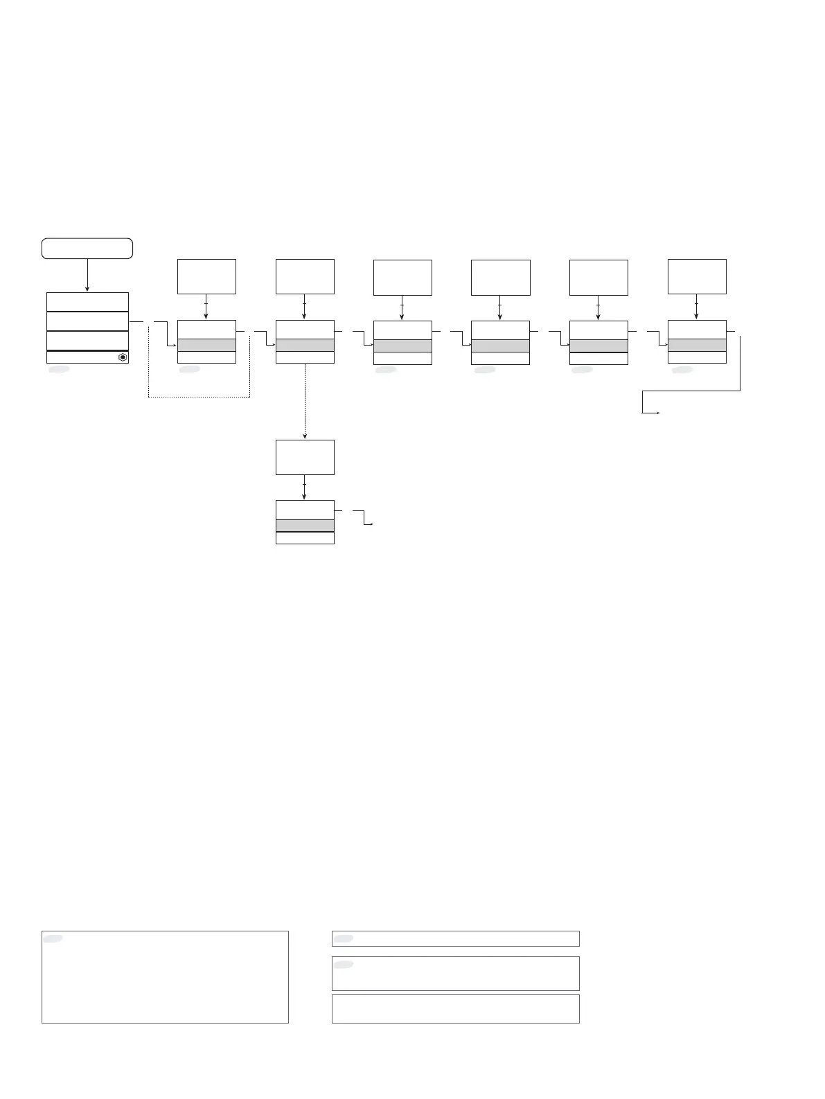
18 9106 - Product version 9106-002
Routing diagram
If no key is activated for 1 minute, the display will return to the default state 1.0 without saving configuration changes.
1 Increase value / choose next parameter
2 Decrease value / choose previous parameter
3 Save the chosen value and proceed to the next menu
Hold 3 Back to previous menu / return to menu 1.0 without saving.
To default
state 1.0
Continued on the page
Routing diagram ADV.SET
*1.1
Only if password-protected.
*1.0
Default state.
Line 1 shows status for channel 1 and channel 2
Line 2 shows analogue value or tag no. for channel 1.
If the loop limit is exceeded (LO.LIM and HI.LIM) the analog
value is shown for 5 sec. followed by txt 18.
In case of loop break, 0.0 is shown for 5 sec. followed by
txt 19.
Line 3 shows the same as line 2, only for channel 2.
Line 4 shows status for communication.
*1.2
Loop current limits (identical for both .channels) can be
deactivated by selecting values outside the range
3.5...23 mA.
Line 1 symbols:
= OK. Flashing
= error.
Power up