22
PM-833TV 4-13-21V1.indd Copyright © 2021 Quality Machine Tools, LLC
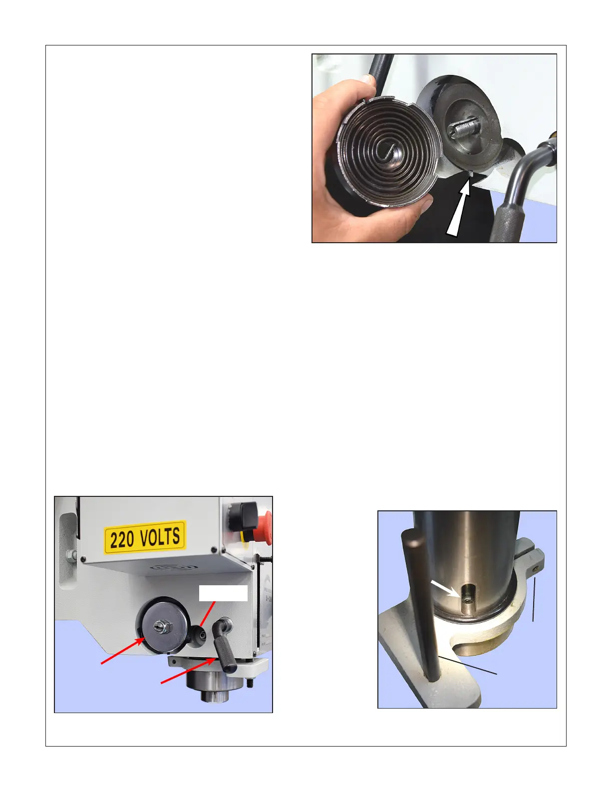
Figure 4-9 Return spring housing & stop pin
R8 COLLET LOCATING SCREW
R8 devices are located in the spindle by a set screw that
protrudes less than 3/32" beyond the inner wall of the
quill. The depth of the locating groove on R8 tooling var-
ies widely, in some cases slightly below spec. If your R8
devices meet spec, but consistently bind when inserted,
the inner screw may be in too far.
Early models of the PM-833TV came with a hex lock nut, Fig-
ure 4-10, to lock the screw in place. The lock nut is not acces-
sible without removing the entire quill and spindle assembly.
Figure 4-10 R8 locating screw
Quill
bracket
clamp
Depth
stop rod
How much return spring force?
There is no hard and fast rule. Most users set the spring
so that the quill can be fully extended without undue ef-
fort, returning close to zero extension when released,
assuming only a collet is installed (no drill chuck).
lube lines on either side of the headstock remain
clear of the leadscrew support block. Place scrap
wood under the spindle to protect the table in case
of accidents.
2. Fully retract the quill, then clamp it in place with
the locking lever, Figure 4-8. Wear leather gloves
throughout the following procedure.
3. While holding the spring housing in place, remove
the self-locking nut from the spring end of the quill
pinion shaft.
4. Using heavy duty needle-nose pliers, grasp the
spring tab outside of the spring housing. Bearing in
mind the sudden turning force stored in the spring,
ease the housing outwards, clear of the stop pin,
Figure 4-9, then relax the spring by allowing the
housing to spin.
Reinstalling the spring
1. Align the center tab of the spring with the slot in
the pinion shaft, then push the spring housing in to
engage the shaft, stopping with the housing rim just
outboard of the stop pin.
2. Using needle-nose pliers grasp the spring tab out-
side of the housing, then rotate the housing count-
er-clockwise to apply tension (the nose of the pliers
will be running in the gap between spring housing
and the machined cavity). When sucient tension
has been applied, ease the housing around a little
more, enough to align the stop pin with a notch in
the housing. Push the spring fully home, seating it
squarely in the machined cavity. Plan on rotating the
spring housing at least one-half turn.
3. Replace and tighten the self-locking nut.
4. Unlock the quill to test the return spring function.
Re-tension if necessary to achieve the desired
spring force.
Figure 4-8 Quill return spring
Return
spring
housing
Quill
locking
lever
Dog screw

 Loading...
