8
PM-833TV 4-13-21V1.indd Copyright © 2021 Quality Machine Tools, LLC
7. Run a sling "basket style" under the headstock.
Wrap a soft cloth around the sling to prevent
damage to the paintwork and the tilt scale. If head-
room is limited use the shortest sling available. It
may also be desirable to remove the motor to allow
extra room (the motor is heavy). Make certain that
the sling, when taking the load, is clear of any deli-
cate components — use spreaders if necessary.
8. Very slowly lift the mill, controlling any tendency for
it to swing as it clears the pallet.
9. Remove the pallet, then install the four leveling
mounts, Figure 2-3.
10. Lower the mill to the oor.
11. Remove the wood blocks supporting the hoist.
12. Raise the mill just clear of the oor, then roll the mill
to its working location.
FINAL ASSEMBLY & CLEANUP
Unnished metal surfaces are protected by thick grease
and/or paper. Carefully remove these using a plas-
tic paint scraper, disposable rags and a light-oil type
degreaser such as WD-40. Level the mill using the ta-
ble surface for reference. Oil the ways and leadscrews.
Check the sight glass for gearbox oil level.
Assemble the support plate for the accordion-pleated
cover, as in Figure 2-6, then attach the support plate to
the top of the column with two M6 socket head screws.
Suggestion If the mill is in a location where dust or
debris can fall from the ceiling, it is a good idea to cover
the column with a 7-1/2 x 3-1/2" plate of scrap material.
MOVING THE MILL (using lifting eyes)
The four lifting eyes provided with the mill allow other
lifting choices, Figure 2-5. They can be hooked directly
to steel cables, or used with 1" diameter steel rods, long
enough (30" plus) to allow chains to be attached at both
ends. A forklift is another option if steel rods are inserted
through the eyes.
Figure 2-5 Lifting eyes
POWER ASSIST OPTIONS
Power-feed motors are available for the table (X-axis)
and headstock (Z-axis elevation). These are stand-
alone units trademarked ALIGN. Both are powered by
110 Vac. The dc motors in these units have twin carbon
brushes that should be inspected occasionally and re-
placed if worn. The motors may be installed on the mill
as-shipped. If not, see the installation instructions at the
end of the Section 4.
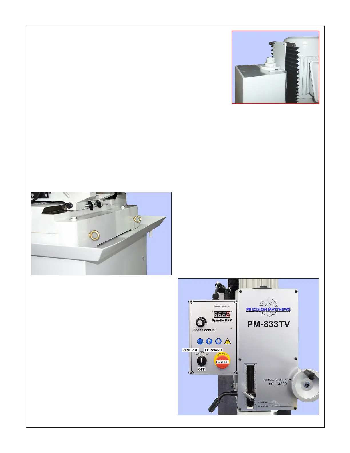
POWER-UP PROCEDURE
Depending on the available 220V wall outlet, install a
6-15 or 6-20 plug on the mill power cord. Connect the
"hot" wires (black/red, black/brown, blue/brown or black/
white) to the at blades. Connect the green/yellow
ground wire to the central U-shaped prong (this wire
may be tagged PE = Protective Earth).
Before connecting 220V power be sure that:
1. The spindle motor switch, bottom left of the front
panel, is set to its midpoint, OFF, Figure 2-7
2. There are no clamps or locks on moving parts, Fig-
ures 2-8, 2-9, 2-10.
3. The drawbar has been removed.
Figure 2-6 Accordion-fold cover support
FASTENING THE MILL TO THE STAND
Lower the mill onto the chip tray using tapered drifts to
align the screw holes. Secure the mill with four 100 mm
x 10mm hex head screws and washers (supplied).
Figure 2-7 Front panel

 Loading...
