7
PM-833TV 4-13-21V1.indd Copyright © 2021 Quality Machine Tools, LLC
UNCRATING THE MILL
The PM-833TV mill and stand are usually shipped in
separate containers. In special instances, the mill and
stand may be shipped pre-assembled Before moving
the mill, check the two Special Precautions on the pre-
ceding page: 1. Oil line protruding from the column, Fig-
ure 2-1, and; 2. (if the headstock is power-assisted) Z
axis limit stops.
INSTALLING THE MILL
Check local codes for machine tool fastening require-
ments. If none is specied, the leveling mounts supplied
can be used, Figure 2-3, or the mill stand can be perma-
nently anchored to the oor. The leveling mount screws
are installed, hex heads up, in weld nuts on the stand
wings. The screws are centered by indentations on the
upper surface of the pads.
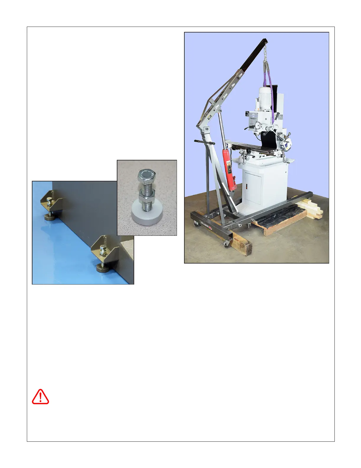
MOVING THE MILL (using slings)
If available, use a forklift to handle the mill. An engine
hoist can be used instead, but this may require some
experimentation along the lines suggested below.
The following notes assume that the mill is pre-in-
stalled on its stand. If the mill and stand were
shipped separately, the engine hoist must have
similar reach and lifting capability to raise the mill
above the surface of the stand.
The main objective of the procedure suggested here is
to lift the mill just enough to allow the pallet to be re-
moved. Thereafter the engine hoist can be used to roll
the mill to its working location.
This is at least a two-person procedure!
Figure 2-4 Using an engine hoist (File photo, Model PM-833)
1. Set the upper arm of the hoist as far out as possible
— but not beyond the point where its lifting capacity
is less than 1500 lb.
2. Remove the lag bolts, etc., securing the mill to the
pallet.
3. Roll the hoist over the pallet to bring the lift chain
directly over the graduated tilt scale at the back of
the headstock, Figure 2-4. Depending on the style of
hoist the legs will likely now be resting on the pallet,
with the casters clear of the oor.
4. At the cylinder end of the hoist insert an 8 x 8 or sim-
ilar wood beam under the legs to raise them clear
of the pallet (lift the hoist by hand, or use a jack).
Beam size is arbitrary, but the legs must be above
the pallet.
5. At the open end of the hoist lift each of the legs in
turn to insert similar wood blocks — or piles of scrap
material as in the photo. (All support material must
clear of the pallet to allow it to be moved away when
unweighted in the following steps).
6. Check that the headstock is fully lowered, spindle
just clear of the table.
Figure 2-3 Supplied leveling mounts
The leveling screws are 1/2-12 TPI, usually unavailable in the U.S.
If extra length is needed, install booster pads under the round pads
supplied.

 Loading...
