21
PM-833TV 4-13-21V1.indd Copyright © 2021 Quality Machine Tools, LLC
DOWNFEED RETURN SPRING TENSION
The quill should automatically retract when the coarse
downfeed levers are released following a drilling oper-
ation. If not the return spring, Figure 4-8, may need to
be re-tensioned or replaced – but rst check for other
issues such as obstructions or lack of lubrication.
Take extra care when working on the spring – it
can unwind violently if not properly controlled
A stop pin in the headstock casting engages in one of
4 notches on the rim of the cup-shaped spring housing,
Figure 4-10. The inner tab of the spring ts into a slot in
the quill pinion shaft. A suggested procedure for adjust-
ing spring tension, or replacing a broken spring, follows.
1. Lower the headstock to bring the spindle nose close
to the table. Don't overdo this — be sure that the
GIB ADJUSTMENT
Gibs on the X, Y and Z axes control the t of the mating
dovetailed surfaces. They are gently-tapered lengths of
ground cast iron located by opposing screws at each
end. Adjusting them is a trial and error process that
takes time and patience. Aim for the best compromise
between rmness and reasonably free table movement.
Too tight means accelerated wear on the ways, lead-
screws and feed motors, if installed. Too free means
workpiece instability, inaccuracies and chatter.
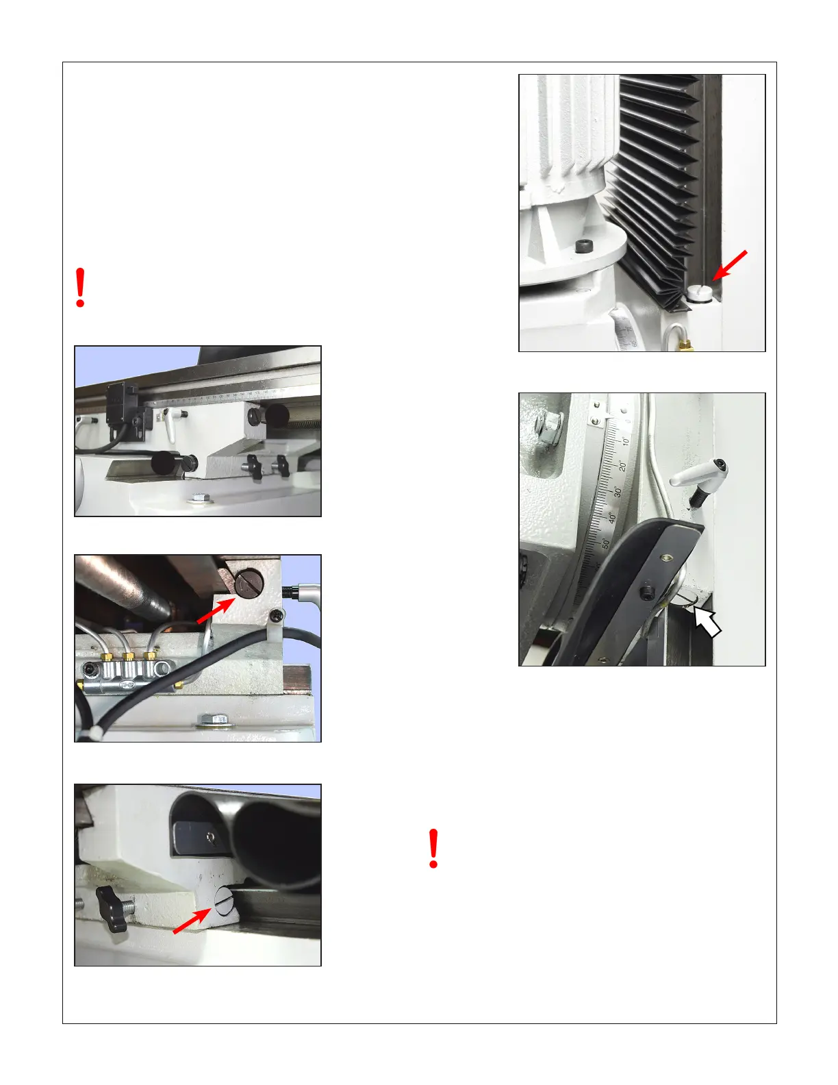
BOTH gib screw heads must be tight against
the gib ends. If you loosen one, tighten the oth-
er. Remove the way covers for access to the
back of the Y gib and bottom of the Z gib.
Figure 4-3 Gib screws: X-axis RH (1), Y-axis front (2)
Figure 4-4 Gib screw: X-axis, LH
Figure 4-5 Gib screw: Y-axis, back
1
2
Figure 4-6 Gib screw: Z-axis, top
Figure 4-7 Gib screw: Z-axis, bottom

 Loading...
