9
PM-833TV 4-13-21V1.indd Copyright © 2021 Quality Machine Tools, LLC
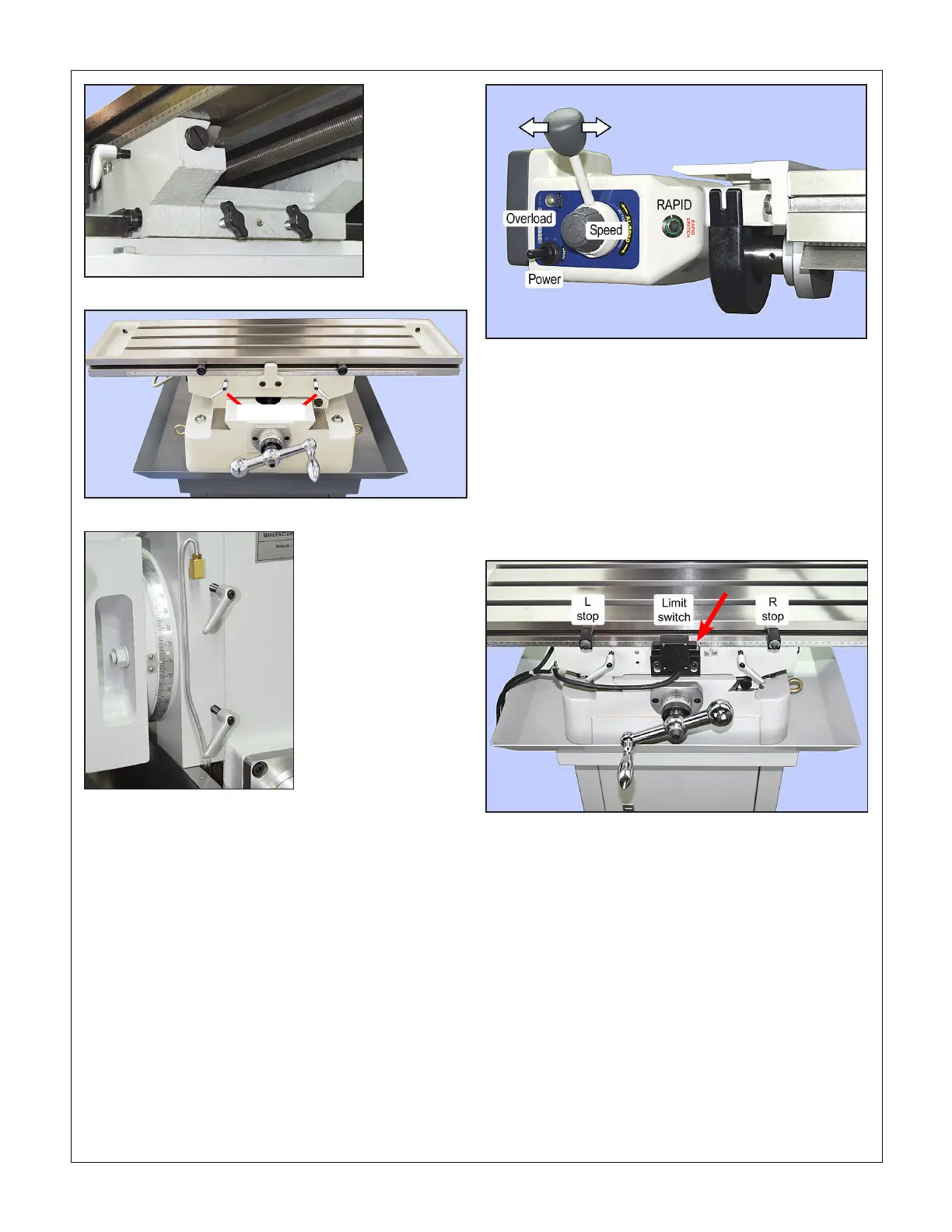
Figure 2-9 X-axis stops and clamp levers
Figure 2-10 Headstock clamp levers
Figure 2-8 Y-axis clamp screws
Before connecting 110V power to the X and Z-axis
power assist units, if installed, be sure that:
1. The power switch on each of the power units is set
to OFF, example Figure 2-11.
2. The speed control on each power unit is set fully
counter-clockwise (lowest speed).
3. The direction control lever on each power unit is
centered (STOP).
4. The X and Z axes can be manually cranked without
diculty — clamp levers loosened.
If power assist units are installed, test as follows:
TABLE - X AXIS
1. Rotate the speed control knob fully counter-clock-
wise, then clockwise about 45 degrees to set a low
speed.
Figure 2-11 Table power assist
2. Switch the table power-assist motor on. Test the
power traverse function by selecting Left traverse,
followed by stop (center), then Right.
3. While running the table to the left, check that the lim-
it switch stops motion when the right-hand plunger is
pressed, arrow in Figure 2-12.
4. Test the left limit switch in the same way. If either
test fails, service attention is required.
5. Test the fast traverse function (RAPID push button
on the motor).
HEADSTOCK - Z AXIS
1. Rotate the speed control knob fully counter-clock-
wise, then clockwise about 45 degrees to set a slow
speed, Figure 2-13.
2. Switch the Z-axis power-assist motor on. Select UP
motion (arrows, Figure 2-13).
3. While running the headstock slowly up the column,
press the upper plunger of the limit switch assembly,
Figure 2-14. Headstock motion should stop immedi-
ately, resuming when the plunger is released.
4. Check for no obstructions, then test the down limit
function in the same way. If either test fails, service
attention is required.
5. Test the fast raise/lower function (RAPID push-but-
ton on the motor).
Figure 2-12 X axis power assist limit switch & stops
Clamp levers

 Loading...
