DCX 800.5
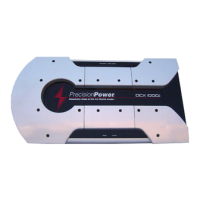
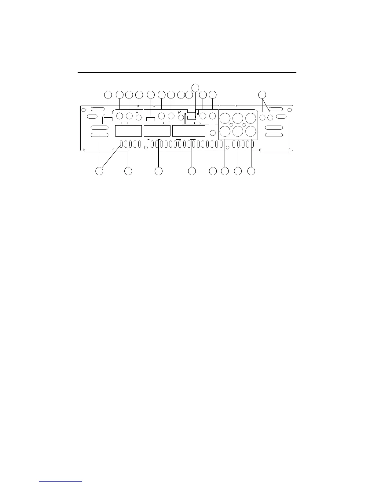
FRONT PLATE DIAGRAM
1. Cooling Plenums: Maintain a minimum 2” clearance around
cooling plenums for proper amplifier cooling.
2. Sub Speaker Connector: Plug in the
PowerLock
TM
connector
here.
3. Rear Speaker Connector: Plug in the
PowerLock
TM
connector
here.
4. Front Speaker/Remote Connector: Plug in the
PowerLock
TM
connector here.
5. -12dB Attenuation Switch: Push this switch ‘IN’ for high voltage
input (4V-12V) capability. This button must be pushed ‘IN’ for use
with speaker level input on common ground head-units or for high
voltage line drivers.
6. Sub Input: Plug in the front RCA leads from your source unit
here.
7. Rear Inputs: Plug in the rear RCA leads from your source here.
8. Front Inputs: Plug in the front RCA leads from your source input
here.
9. QBASS
TM
1 and QBASS
TM
2 Freq.: Use these switches,
QBASS
TM
1
and
QBASS
TM
2
to program the
QBASS PLUS
TM
circuit
frequency.
10. Front Gain: Use this control to match the output level of the
source unit to the front channel of the amplifier.
11. Front Freq. Control: Move this detented control in a clockwise
direction to adjust the front crossover frequency from 30Hz to4kHz.