C932, C932i, C934, C936i Treadmilll
Page 26
Procedure 5.3 - Troubleshooting the Speed Sensor
Note:
The speed sensor is a hall effect sensor that emits a pulse when a flywheel lobe passes between
it’s transmitter and receiver. The speed control circuit processes the pulse train emitted by the
speed sensor. The speed sensor signal is a real time representation of the operating speed of
the treadmill. The speed control circuit compares the real time speed (speed sensor output) with
the speed that it expects the treadmill to be operating at and acts accordingly to control treadmill
speed or initiate an error code sequence, if necessary. Typically, if a problem exists with the
speed sensor the drive motor will operate (perhaps only briefly) before a speed related error
occurs (errors 20-26).
1. Set the treadmill circuit breaker in the “on” position. Using a DC voltmeter, measure the
voltage between terminal 3 of J3 (green wire) and terminal 4 of J3 (black wire) on the lower
PCA. Slowly, rotate the drive motor flywheel. The voltage should read approximately 0.25
Vdc when a flywheel lobe is between the speed sensor “legs” and approximately 5 Vdc
when a flywheel lobe is not between the speed sensor “legs”.
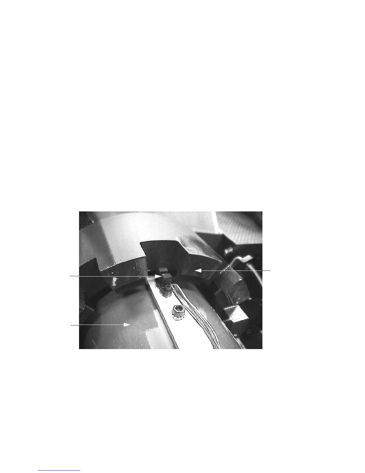
Diagram 5.3 - Speed Sensor Mounting
2. If the voltages in step 1 are correct, go to step 5. If the voltage in step 1 is 0 Vdc or
significantly low when a flywheel lobe is between the speed sensor “legs’, continue with step
3.
Flywheel
Lobe
Speed
Sensor
Drive
Motor