© Precor Incorporated, Unauthorized Reproduction and Distribution Prohibited by Law Page 2
Contents
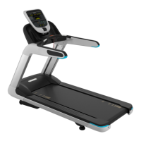
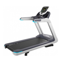
TRM 800v.2 Series Treadmill ........................................................................................................ 7
Lubricants ...................................................................................................................................... 7
Electrical Requirements ................................................................................................................ 7
US and Canada power requirements ................................................................................ 8
PVS (Personal Viewing Systems) Equipped Units .............................................................. 9
P80/P82 Console Equipped Units ......................................................................................... 9
RF (CATV) Requirements ....................................................................................................... 9
Internet Ethernet Requirements ........................................................................................... 9
Power Input ................................................................................................................................. 10
Nominal 120V systems .......................................................................................................... 10
Nominal 230V systems .......................................................................................................... 10
Procedure .............................................................................................................................. 12
Operation Verification Checklist .................................................................................................. 13
Service Access Codes ................................................................................................................ 14
Accessing the Service Software .................................................................................................. 14
P80 Console ........................................................................................................................... 14
Service Access Codes ................................................................................................................ 15
Hardware Validation Settings (51765761) .................................................................................. 15
Club Parameter Settings (5651565) ............................................................................................ 16
Information Display (65) .............................................................................................................. 17
Consoles ...................................................................................................................................... 19
Basic operation of a console ............................................................................................. 19
Optional TRM800.v2 Base Consoles .................................................................................. 20
Console to Base Communication ................................................................................................ 20
Bleed Resistor ............................................................................................................................. 22
A 1MΩ 1500V bleed resistor between the secondary ground and earth ground is
required for voltage stabilization. ...................................................................................... 22
Dynamic Brake (DB) Resistor ..................................................................................................... 22
Dynamic Brake resistor overload detection (Thermal sensing) ................................... 22
Dynamic Brake resistor detection circuit. ........................................................................ 22
Dynamic Brake thermal switch .......................................................................................... 23

 Loading...

