SDI-JC-22D2 rev. 11-1-21 page 6 of 22
Installation
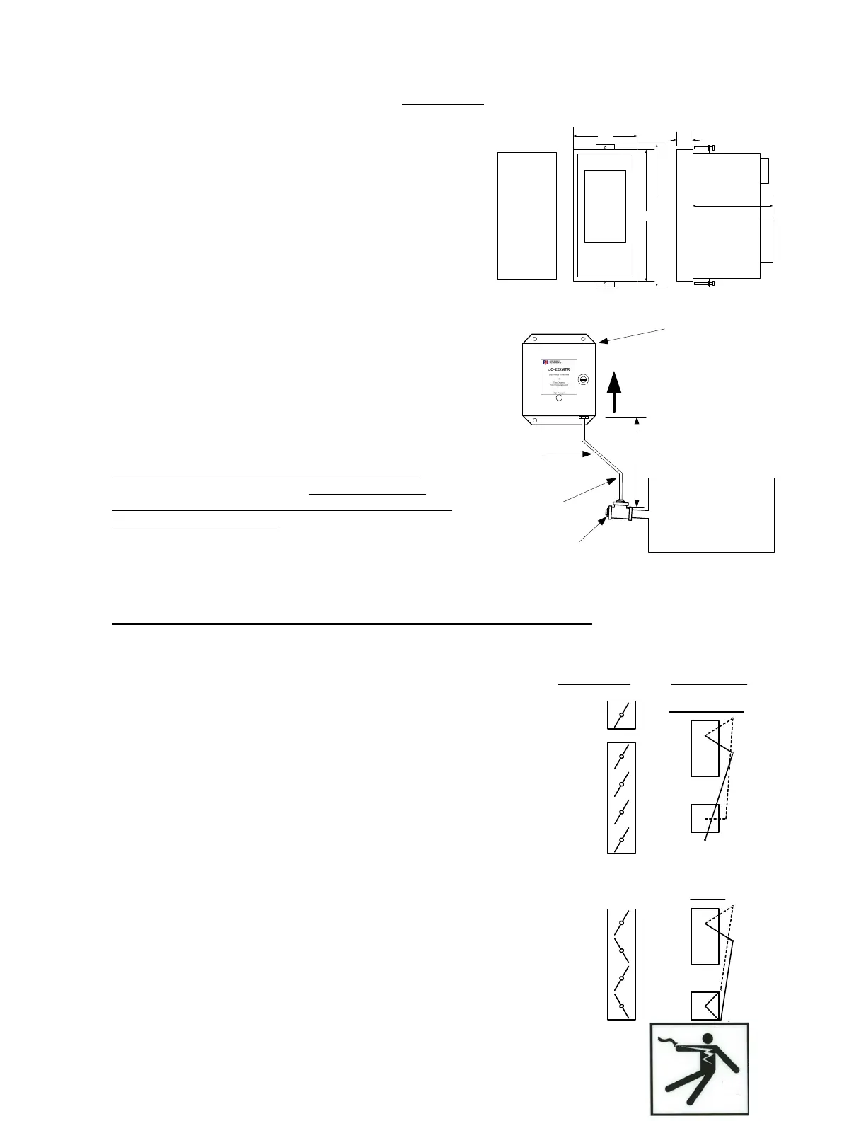
JC-22D2 Indicator Mounting:
The JC-22D2 Indicator is designed for flush mounting in an enclosure
located rated NEMA 12 or better.
The JC-22D2 should not be subjected to excessive vibration.
Continuous operation is guaranteed over the 32-131 F (0-55C) ambient
operating range.
JC-22XMTR-xxCO Mounting
The JC-22XMTR-xxCO is the standard xmtr for use with the
JC-22D2. Other 4-20 mA xmtrs may be used with the JC-22D2.
Mount the transmitter in a location that is free from excessive
vibration and that will remain at a stable temperature. To prevent
incorrect pressure measurements, the pressure tap in the duct
should be flush with the inside wall of the duct and should be
perpendicular to the primary flow pattern.
Burner flue gas contains a significant amount of water vapor, which
condenses inside the impulse tubing. If the condensed water
collects and remains in the impulse tubing, a false higher pressure
will be applied to the transmitter, which will cause improper draft
control system operation and/or nuisance burner trips.
Mounting the JC-22XMTR close to the pressure tap minimizes
condensate drainage problems.
See the SDI-JC-22XMTR-xxCO instruction manual for additional important installation details.
Damper Actuator Linkage:
The linkage arrangement between the servo actuator and the damper is
important. The wrong arrangement can make it very difficult to control the
draft at reduced firing rates.
Single blade and Parallel blade dampers have a very non-linear flow vs.
rotation characteristic. Rotating from fully closed toward open, the flow
increases very rapidly as the damper opens. The flow changes much less
near the fully open end of the rotation.
The linkage for single and parallel blade dampers should be arranged in a
'Slow Opening' configuration in order to linearize the draft control loop. Near
the Closed position, the servo rotation opens the damper very slowly.
Opposed blade dampers have a more linear flow vs. rotation characteristic.
The linkage for a properly sized opposed blade damper should be between
Linear. Oversized opposed blade dampers may require a Slow Opening
linkage arrangement.
Furnace
or
Flue Gas Duct
UP
12"
minimum
Pitch Down
2" per foot
(minimum)
for drainage.
Pressure Tap with
Clean-out Plug (1-1/4" pipe typ.)
JC-22XMTR
Must be located
ABOVE the flue gas
tapping for proper
condensate draining
Impulse Line
See text for size
Single
Blade
Parallel
Blade
Damper Style: Linkage Setup:
Damper
Servo
Slow Opening:
O
C
C
O
Opposed
Blade
Damper
Servo
Linear:
O
C
C
O
Panel Cutout
3.61 x 7.65
3.88
8.00
Touch
Screen
8.74
Plug-in Terminals
1.00
4.88
Plug-in Terminals