SDI-JC-22D2 rev. 11-1-21 page 9 of 22
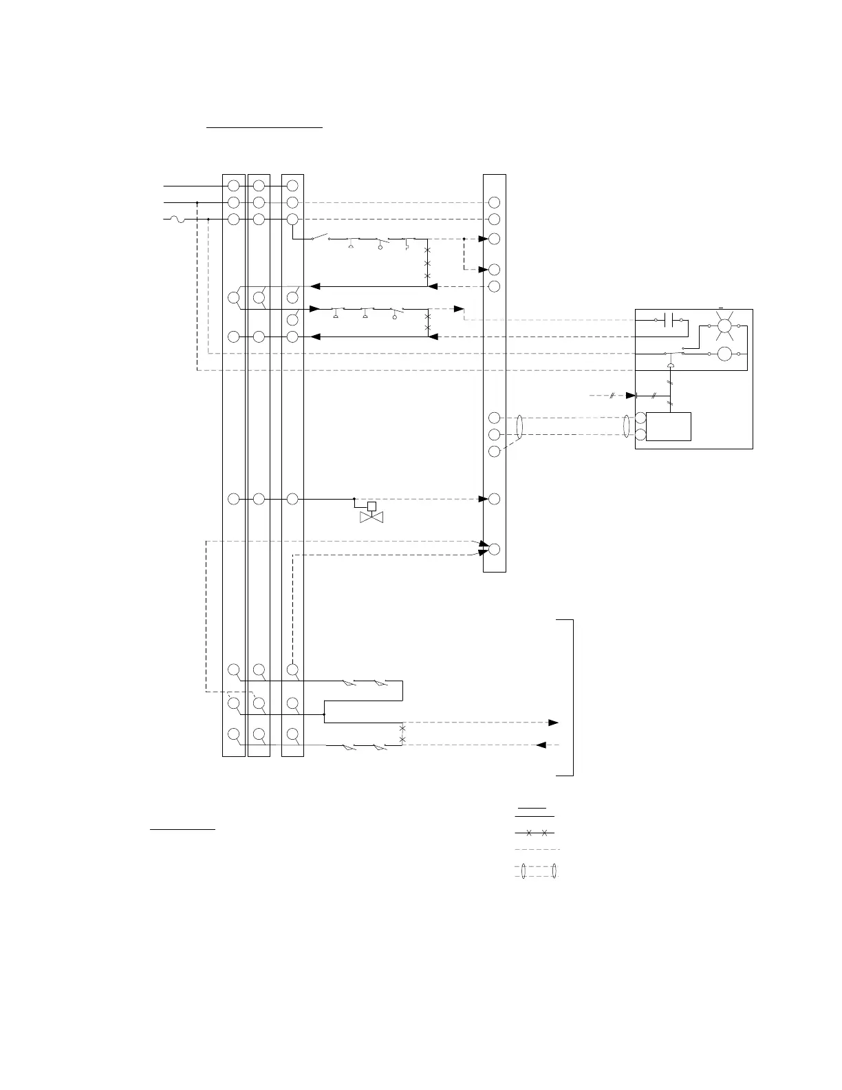
Typical JC-22D2 Interfacing to a Burner Flame Safeguard
L1
L2
G
3
P
JC-22D2
Draft
Controller
35
36
39
+24 V
+
-
4
L2
G
L1
L2
G
L1
N
Draft Sensor and
High Pressure Switch
Model: JC-22XMTR-xPCO
15
9
10
6 13
Operating Limit
Fan Start
Delay
Contacts
Non-Recycling / Lockout Limits
3
7 P
Draft / Pressure
Connection
T1-1
R
T1
5 sec
Off Delay
blk
wht
red
red
4-20 mA
" WC Xmtr
+
-
1
2
Low Voltage DC
Do not run in Conduits with AC
H
N
G
120 Vac
60 Hz
26 VA
Fireye
E100/E110
Honeywell
RM7800L
Existing Burner Flame Safeguard:
WARNING:
* Some Flame Safeguard Wiring is Omitted for Clarity.
* Consult Burner Manual for Complete Wiring Diagram.
* An Experienced Burner Technician must adapt this TYPICAL
wiring diagram to each specific burner wiring diagram.
Fireye
YB110
Safety Interloc k (required by Co de)
Burner
Flame
Safeguard
120 Vac
60 Hz
99 7 13
8
M
D
8
Low Fire Proving Switches
Purge Proving Switches
Fan
Fan
Fuel Valve
Fuel Valves
Draft Purge Interlock (required by Code)
Fireye
E100/E110
Honeywell
RM7800L
Fireye
YB110
D
M
8
18
5
19
RM7800 / YB110
E100 / E110
For Draft Damper Actuator
and ID Fan VSD wiring
See sheet 2
For Additional Options
See sheet 3
Fan
Operating Limits
Legend:
Existing AC Wire (Do NOT change this wiring)
Remove Existing AC Wire
New AC Wire
New Shielded Low Voltage DC Cable
Do Not Run in Conduits with AC Wires