Pressure Systems, Inc. NetScanner™ System (9016, 9021, & 9022) User’s Manual
www.PressureSystems.com
5 - 19
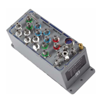
Figure 5.8
PC-317 Board (Trim Potentiometer and Jumper
5.2 9022 Excitation Trim
The 9022 output voltage is factory set at 10 volts. The following procedure can be used to trim
the 10 volt output (~±5%).
(1) Disassemble the unit as described in Section 5.1.2.
(2) Locate R-19, the output voltage trim potentiometer, on the PC-317 board. It is the only
potentiometer on the board and is near the end of the unit on the top side of the lower PC
board (PC-317), toward the end of the unit nearest the main power and communications
connector. Note that R-19 is a four turn potentiometer. See Figure 5.8, below.
(3) Place the disassembled unit on a nonconductive surface. Using a spare connector,
connect a calibrated voltage meter to pins G and H (+ and - respectively) of any of the
transducer connectors.
(4) Apply power to the unit through the main power and communications connector. The 10
volt output voltage may be trimmed by rotating the potentiometer R-19.
(5) Once the output voltage is set, remove power from the unit.
(6) Reinsert the electronics into the housing, ensuring that the alignment posts in the
module’s bottom panel align with the holes in the PC-280 mounting brackets. This may
require loosening the three (3) screws attaching the PC-280 board to the top plate