Do you have a question about the Pressure Systems NetScanner 9116 and is the answer not in the manual?
Provides an overview of the Model 9116 scanner and its purpose.
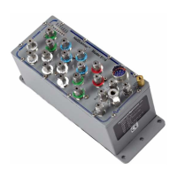
Describes the Model 9116 instrument, highlighting key features and specifications.
Details the electronic and feature differences between Model 9016 and Model 9116.
Lists optional configurations and add-ons available for the Model 9116 scanner.
Details available full-scale pressure ranges for DH200 transducers, which can be mixed.
Describes manifold types and pneumatic connection fitting options for the scanner.
Explains the communication interfaces, including Ethernet TCP/IP and UDP/IP protocols.
Provides instructions for unpacking and inspecting the Model 9116 scanner module.
Outlines essential safety precautions for operating and handling the equipment.
Details steps required to prepare the scanner for operation, including environment.
Specifies environmental conditions required for accurate operation and to prevent damage.
Details the power supply requirements and connection for the Model 9116 scanner.
Provides information on mounting the module and its physical dimensions.
Explains how to connect the scanner to a network via its Ethernet port.
Details the connection procedures for the diagnostic RS-232 serial interface.
Describes pneumatic connections to the Model 9116 for pressure input.
Explains the pneumatic input connections for the RUN mode operation.
Details the pneumatic input connections for the CAL (Calibration) mode.
Explains the pneumatic connections and procedure for the PURGE mode.
Details the pneumatic connections and procedure for the LEAK-CHARGE mode.
Specifies the requirements for the dry air supply needed for calibration valve operation.
Describes the case grounding feature for electrical noise reduction.
Explains the use and configuration of the data acquisition synchronization trigger signal.
Details the self-diagnostic checks performed by the module upon power-up.
Introduces commands and responses for the Model 9116 scanner.
Outlines the scope and content of the programming and operation chapter.
Explains the fundamental structure and types of commands used with the scanner.
Details the typical format of TCP/IP commands, including fields and syntax.
Describes the command field, typically a single alphabetic letter for TCP/IP commands.
Explains how the position field is used to identify channels via a bit map.
Describes the datum fields used for sending or receiving data in commands.
Explains the format field parameter that governs data conversion and representation.
Details the types of responses a module can return: Error, Acknowledge, Data, Query.
Explains how to interpret offset values returned after a Re-zero calibration.
Explains how to interpret gain values returned after a Span calibration.
Explains how to obtain pressure data in different engineering units (e.g., psi, kPa).
Classifies commands into functional groups for easier understanding.
Provides a comprehensive reference for all commands applicable to the Model 9116.
Introduces the calibration process and the polynomial formula used for pressure conversion.
Explains the process of performing a Re-zero adjustment to correct offset drift errors.
Details how the calibration valve is controlled during the Re-zero process.
Provides a step-by-step summary for executing a Re-zero calibration.
Explains the process of performing a Span calibration to adjust gain coefficients.
Details how the calibration valve is controlled during the Span calibration process.
Provides a step-by-step summary for executing a Span calibration.
Describes the comprehensive Multi-Point Calibration function for offset and gain adjustment.
Explains valve control for Multi-Point Calibration, noting manual setting.
Provides a step-by-step summary for executing a Multi-Point calibration.
Explains how to store calibration coefficients to non-volatile memory.
Warns about pressure transients when shifting the calibration valve.
Provides guidance on repair and maintenance of the Model 9116 Intelligent Pressure Scanners.
Details common maintenance tasks and precautions, including ESD protection.
Provides step-by-step instructions for disassembling the scanner module.
Guides on replacing the main, daughter, and analog circuit boards.
Detailed procedure for replacing the PC-327 Analog PCB.
Procedure for replacing the PC-322 Main Board and PC-323 Daughter Board assembly.
Specific instructions for removing and replacing the PC-323 daughter board from the PC-322.
Step-by-step guide for replacing the internal DH200 pressure transducers.
Procedure for replacing the calibration valve solenoid valves.
General procedures for replacing O-rings in calibration valves and components.
Detailed steps for replacing O-rings on the DH200 pressure transducer.
Procedure for replacing O-rings on the tubing plate assembly.
Procedure for replacing O-rings on the adapter plate of the calibration manifold.
Steps for replacing O-rings on the calibration manifold pistons.
Procedure for replacing O-rings within the internal solenoid valves.
Information on how to upgrade the scanner's internal firmware.
Details upgrading firmware using the Ethernet Host Port and PSI software.
Guides for troubleshooting issues related to the Ethernet interface.
Verifies the power-up sequence and LED status for correct operation.
Diagnoses issues with establishing TCP/IP communications with the scanner.
Explains methods for assigning IP addresses for Ethernet communication.
Details host computer IP address configuration for Windows OS.
Addresses common errors and problems during zero and gain calibration procedures.
Introduces the NetScanner Unified Startup Software (NUSS) for operating the system.
| Accuracy | ±0.05% FS |
|---|---|
| Number of Channels | 16 |
| Communication Interface | Ethernet |
| Pressure Range | Up to 3000 psi |
| Operating Temperature | 0 to 50°C |
| Resolution | 0.001% of full scale |
| Power Supply | 100-240 VAC, 50-60 Hz |