Pressure Systems, Inc. NetScanner™ System (9016, 9021, & 9022) User’s Manual
www.PressureSystems.com
2 - 12
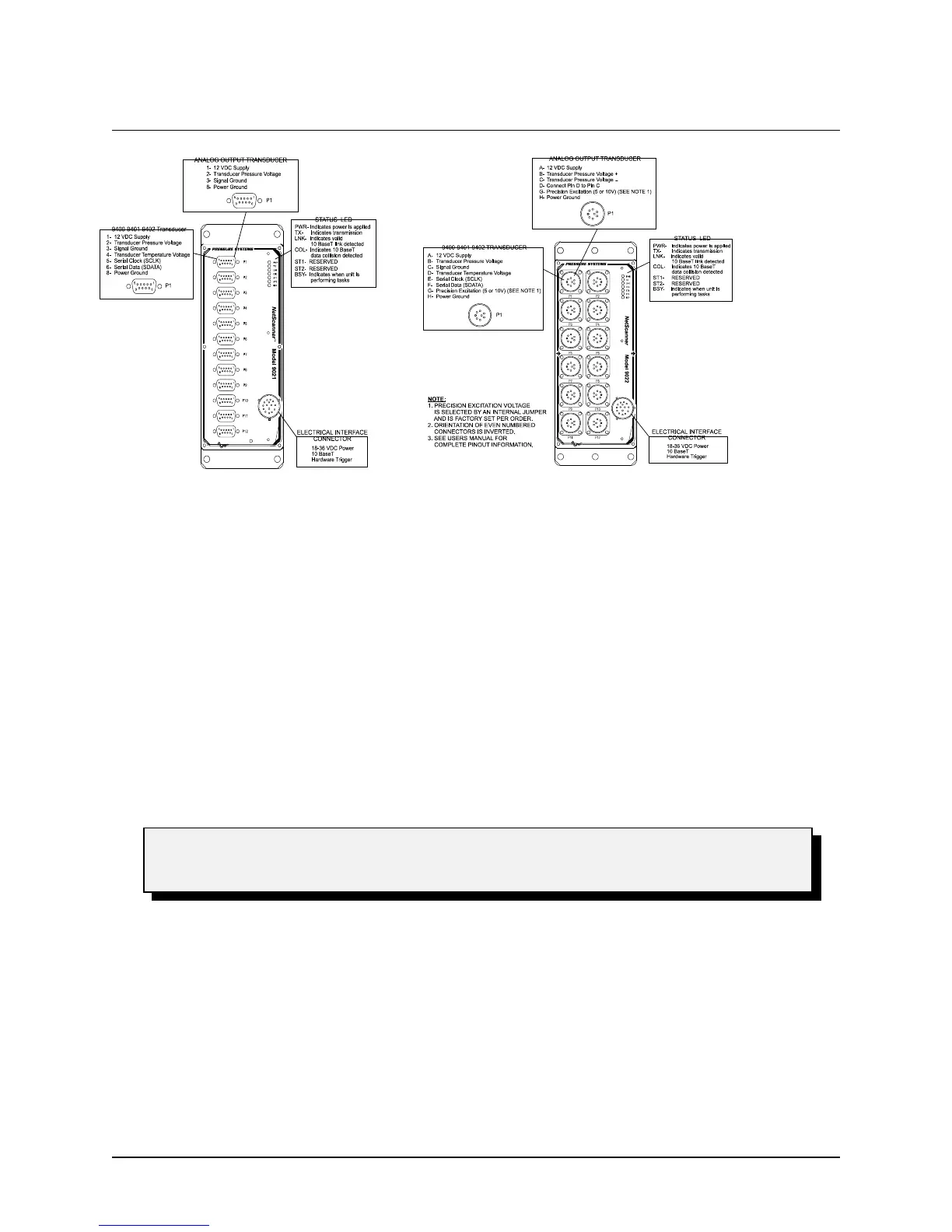
Figure 2.4a
9022 Transducer Wiring
Figure 2.4
9021 Transducer Wiring
Please refer to Section 5.12 for module disassembly instructions if changes to the
excitation voltage are needed.
2.3.7.2 Installation of All Other Transducers
If other analog output transducers are used with the 9021 they must provide an analog output less
than the 9021 maximum input range of ±5 VDC. These transducers can be interfaced to the 9021
as shown in Figure 2.4. When using external transducers, both the 9021 and 9022 modules
provide a +12VDC unregulated supply voltage to power the transducer.
The 9022 has a jumper (JB1) on the PC-317 board for selecting the precision 5 or 10 VDC
excitation source. See Figure 2.5. JB1 is a three-pin jumper. When the two pins closest to the
edge of the board are connected (pins 2 and 3), the configuration is set for 10 VDC excitation.
When the center and the innermost pins are connected (pins 1 and 2), the configuration is set for 5
VDC excitation.