Section 1: Set-Up Requirements
Tractor Requirements
This unit is shipped completely assembled. Carefully follow instructions
for final assembly. Hitch clevises and lock pins are sold separately.
RMX and RMH models are designed with a 3-point category I hitch, which
may be adapted to a category II. The RMS model is designed with a
3-point category I hitch and will require an adjustment to fit a category II
hitch. Horse power rating of the tractor should not exceed the PTO rating
of the gearbox.
*May require the use of hitch bushings.
Three-Point Hitch
See Chart below for Tractor Categories and Three-Point Standards
The stabilizing arms are the 2-steel or cast arms that extend rearward
and provide the lift and are the pull-point for the implement (referred to
as lower link). The Upper Link is the 3rd mounting point and extends
from a top middle position at the rear of the tractor. Comparatively little
rearward force is applied from the top link.
The implement has been designed for front to back flotation while mov-
ing on uneven terrain. Adjust the tractor’s top link to place the upper
hitch vertically above the lower lifting arms.
Tractor Hook-Up
1. If your tractor has a multi-speed PTO, be certain that the PTO is
set for 540 RPM.
2. Back tractor up to implement until lower 3-point links are aligned
with the hitch clevises on your implement. Always stop the trac-
tor, set the brake, shut off engine and remove the key before
dismounting from tractor.
3. Secure tractor’s 3-point lower links to the lower hitch clevises
using 7/8" hitch pins. Use appropriate hitch pins for your hitch
classification. Refer to “Tractor Categories and Three-Point Hitch
Specification” table below.
4. Secure the tractor’s top link to the implement’s top hitch using a
3/4” hitch pin (supplied by customer). Adjust the tractor top link in
order to level the implement.
5. Start tractor engine and lift implement from the ground about 12-
14 inches. Turn off the tractor.
6. Adjust the tractor’s 3-point hitch lift height so that the implement is
not lifted more than 14'' off the ground while the PTO Driveline is
attached to implement and tractor to avoid damaging the driveline.
7. Install the stabilizer arms, anti-sway blocks or chains, refer to your
tractor’s operating manual to limit side sway of hitch. Side to side
oscillation of about 2 inches is recommended.
8. Level the implement at the sides by adjusting the tractor lift links.
9. Measure the blade tip height on both sides, if these are not the
same refer to Section 2 “Adjustments for Deck Mowing Height” on
page 16.
10. Mount the driveline to determine if this needs to be adjusted.
11. Carefully raise and lower the implement and ensure that tractor’s
tires, drawbars, and other equipment on the tractor do not come
into contact with the implement’s frame or PTO Driveline.
12. Use the lift control limiting stop on the tractor control lever to limit
the upward travel of the lever so the lift cannot be raised high
enough to cause contact between the drive shaft shield and front
shielding.
Model
Width
Hitch
Type
Recommended
Maximum HP
FMX500 5'
I/ II*
40
FMX600 6'
I/ II*
50
RMS400 4'
I
40
RMS500 5'
I/ II*
60
RMS600 6'
I/ II*
60
RMX500
5
'
I/ II*
60
RMX600
6
'
I/ II*
75
RMH700 7'
II
90
3
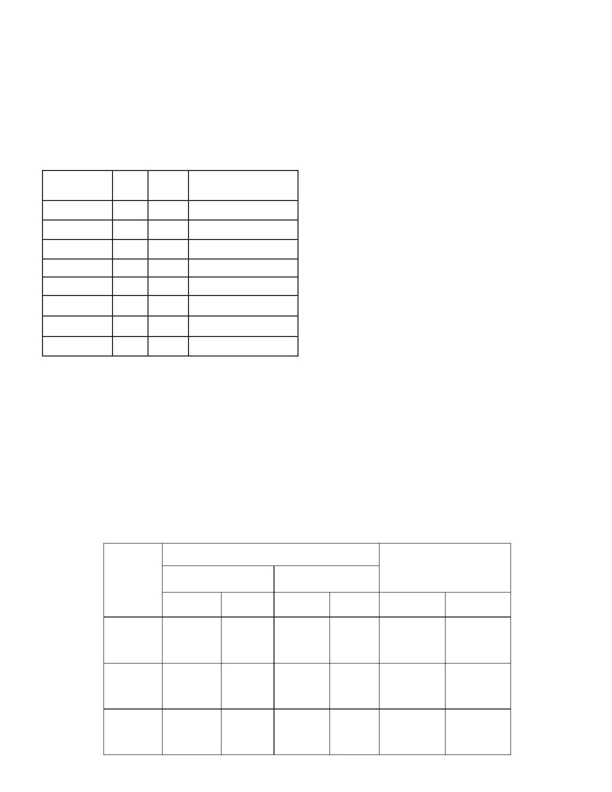
Tractor Categories and Three-Point Hitch Specifications
10
Category
Hitch Pin Size Lower Hitch Spacing
(Spread)
Upper Link Lower Link
Inches Metric Inches Metric Inches Metric
I
3/4”
19mm
7/8”
22.4mm
26”
718mm
II
1”
25.5mm
1-1/8”
28.7mm
32”
870mm
III
1-1/4”
31.75mm
1-7/16”
37.4mm
38”
1010mm