28
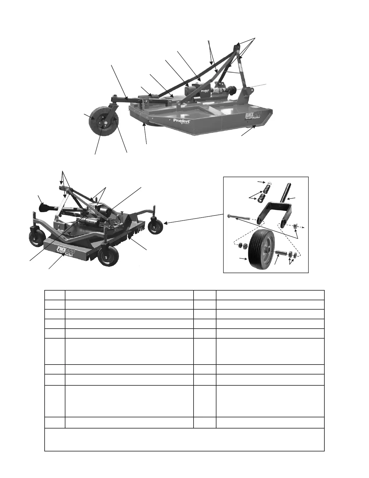
Section 6: Components
5a
5b
10
8
12
7
6
11
4
3
2
1
9
RMS, RMX and RMH Models
FMX Models
8
9
10
12
6
5a
5b
Ref No. Description Ref No. Description
1 Wheel Fork Assembly 10 Gearbox
2 Wheel Hub Assembly 11 Document Canister
3 Tire with Rim 12 Skids
4 Tail A-Frame Assembly 13 Solid Rubber Tires with Rim
5 3-Point A-Frame Assembly
5a—3-Point Front Stabilizer Arms
5b—3-Point Center Yoke,
Yoke Pins & center Point Arms
6a 2-Ply Rubber Guarding (standard on FMX, RMS and RMX)
7 Deck 16 Wheel Assembly Yoke
8 PTO Drivelines with Outer Shielding:
FMX—Driveline with Shear Bolt & Push-Pin Coupling
RMS—Driveline with Shear Bolt and Snap Ring
RMX—Driveline with 2-Plate Slip Clutch
RMH—Driveline with 4-Plate Slip Clutch
9 Gearbox Shield 19
RMS, RMX & RMH—Mower Blades with bolt and Stump Jumpers are not shown
FMX mower blades with spindles, belt and bolts are not shown.
14 Wheel Assembly Adjustment Gauges
2 - 1 in. gauges
3 - 1/2 in. gauges
17
18
1/2" Bolt & Nut
2 - Wheel Bearings
2 - Spacers
Axle sleeve
15 Clevis Pin
14
13
Wheel Assembly Exploded View
15
16
19 18
17