ASSEMBLY
A
ssembly requires two persons.
S
et the treadmill in a cleared area and remove all packing materials.
D
o not
dispose of the packing materials until assembly is completed.
Note: The underside of the treadmill walking belt is coated with high-performance lubricant. During shipping, a
small amount of lubricant may be transferred to the top of the walking belt or the shipping carton. This is a normal
condition and does not affect treadmill performance. If there is lubricant on top of the walking belt, simply wipe off
the lubricant with a soft cloth and a mild, non-abrasive cleaner.
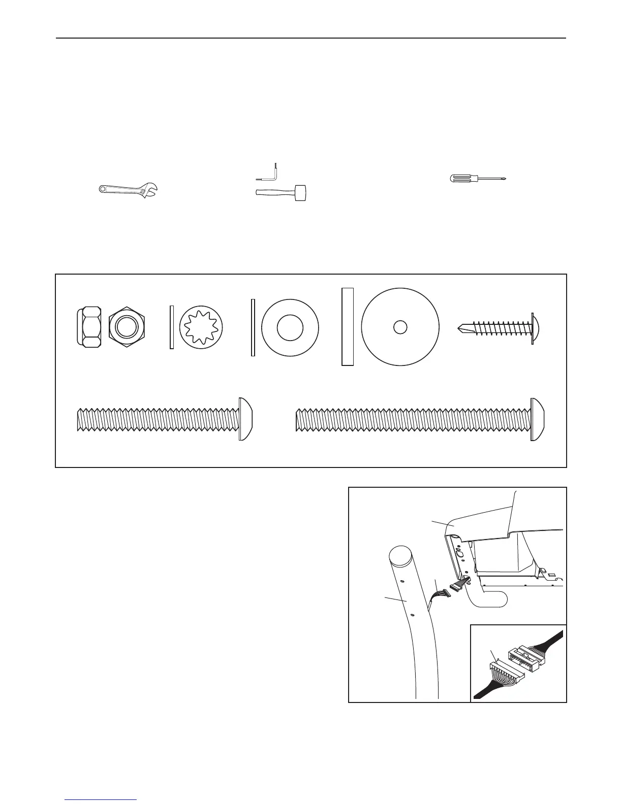
Assembly requires the included hex key and your own phillips screwdriver , adjustable
spanner , and rubber mallet .
For help identifying the assembly hardware, see the drawings below.
The number in parentheses below each
drawing is the key number of the part, from the PART LIST on pages 30 and 31. The number following the paren-
theses is the quantity needed for assembly.
Note: Some small parts may have been preassembled. If a part is
not in the parts bag, check to see if it has been preassembled.
6
1” Tek Screw (82)–4
Washer (96)–8
Console Bolt (72)–4
3
Extension Leg Bolt (87)–4
Star Washer
(67)–4
Nut (106)–4
Plastic Spacer
(101)–4
1. With the help of a second person, carefully raise the
Uprights (85) to the vertical position. Remove the band
securing the Upright Wire Harness (73) to the right
Upright.
Next, have a second person hold the console assembly
near the right Upright (85). Connect the Upright Wire
Harness (73) to the wire harness on the console assembly.
Make sure to connect the connectors properly (see
the inset drawing). The connectors should slide to-
gether easily and snap into place.
If the connectors do
not slide together easily and snap into place, turn one
connector and try again. IF THE CONNECTORS ARE
NOT CONNECTED PROPERLY, THE CONSOLE MAY
BE DAMAGED WHEN THE POWER IS TURNED ON.
Then, insert the connectors down into the right Upright.
73
85
Console
Assembly
73
1