7
3. Attach the Latch Assembly (82) to the Left Upright (84)
with the two Latch Screws (134). Start both Latch Screws
before tightening either of them. Note: The Latch Screws
may be preattached to the Left Upright.
134
84
82
3
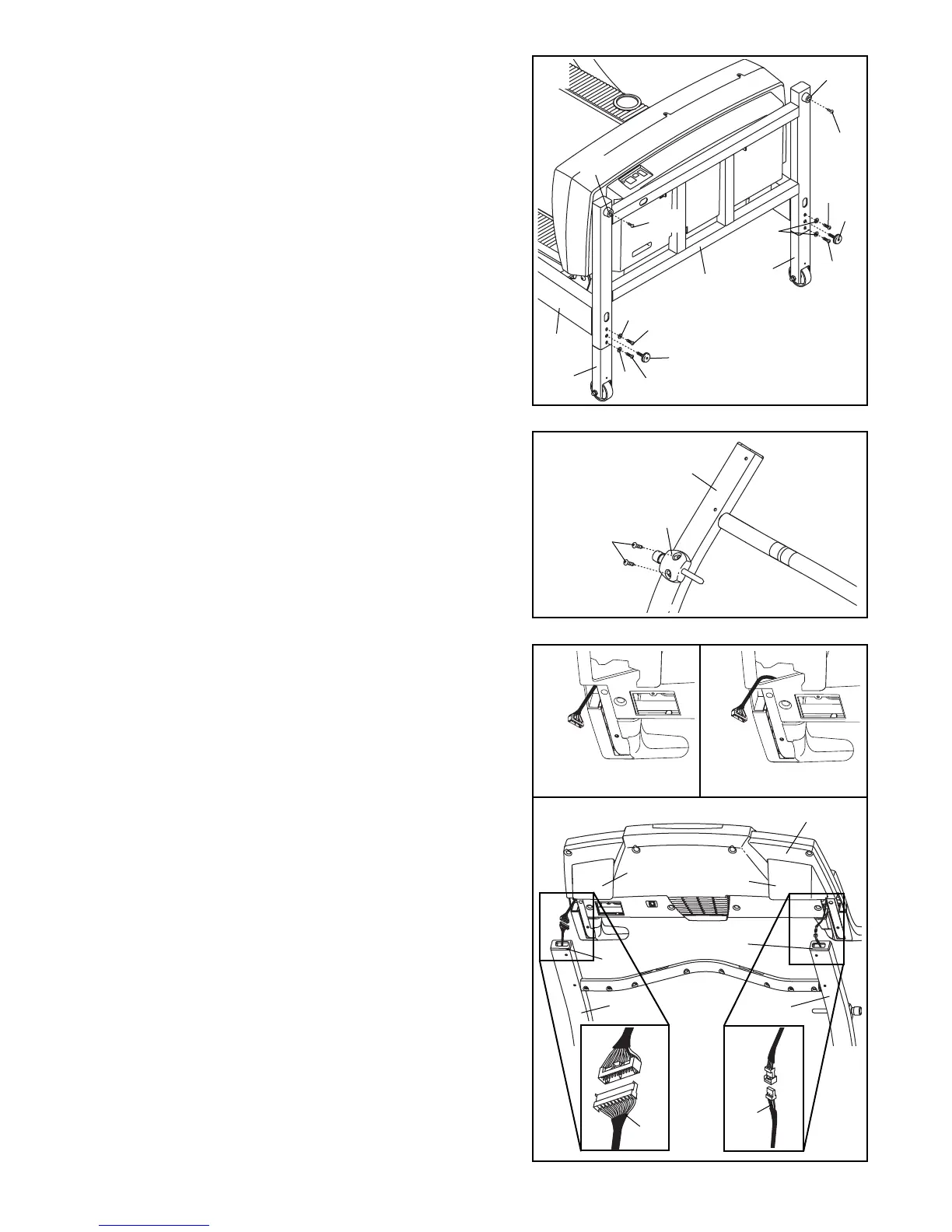
4. See step 6 and locate the four Upright Bolts (86). Loosen
the Upright Bolts two to three turns.
See drawing 4c. With the help of a second person, hold
the Console Base (101) near the Uprights (80, 84). Look
under the Console Base and locate the wires on the
sides of the Console Base. Make sure that the wires are
not routed through the openings for the Trays (109,
111). Drawing 4a shows the correct route for the wires.
Drawing 4b shows an incorrect route.
See drawing 4c. Cut the plastic ties holding the Wire
Harness (74) and the Pulse Wire (153) in the Uprights
(80, 84). Connect the Wire Harness and the Pulse Wire
to the wires on the sides of the Console Base (101).
Make sure to connect the connectors properly (see
the inset drawings). IF THE CONNECTORS ARE NOT
CONNECTED PROPERLY, THE CONSOLE MAY BE
DAMAGED WHEN THE POWER IS TURNED ON. The
connectors should slide together easily and snap
into place. If the connectors do not slide together easily
and snap into place, turn one connector and try again.
Insert the excess Wire Harness and Pulse Wire up into
the Console Base.
101
111
109
80
75
81
84
4a
4b
4c
Correct
Incorrect
153
74
2. With the help of a second person, carefully tip the
Upright Base (97) down as shown. (Note: It may be help-
ful to place your foot on one of the Extension Legs [92]
as you tip the Upright Base.)
Make sure that the
Extension Legs remain in the Upright Base.
Attach each Extension Leg (92) with two Extension Leg
Bolts (96) and two 1/4” Washers (39) as shown. Next,
thread a Levelling Foot (95) into each side of the Upright
Base (97); do not thread the Levelling Feet fully into
the Upright Base.
Attach the two Base Pads (99) to the Upright Base (97)
in the locations shown with two 1” Tek Screws (135).
With the help of a second person, raise the Upright Base
(97) to the vertical position.
96
135
135
99
99
39
96
92
95
95
96
92
96
97
39
39
97
2