11
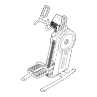
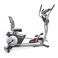
5. Orient the Front Stabilizer (23) so that the widest
sides (B) of the 50mm Square Outer Caps (46)
touch the floor.
Attach the Front Stabilizer (23) to the Front Leg
(25) with two M10 x 65mm Carriage Bolts (16)
and two M10 Locknuts (17); do not tighten the
Locknuts yet.
23
46
46
17
17
25
5
16
B
B
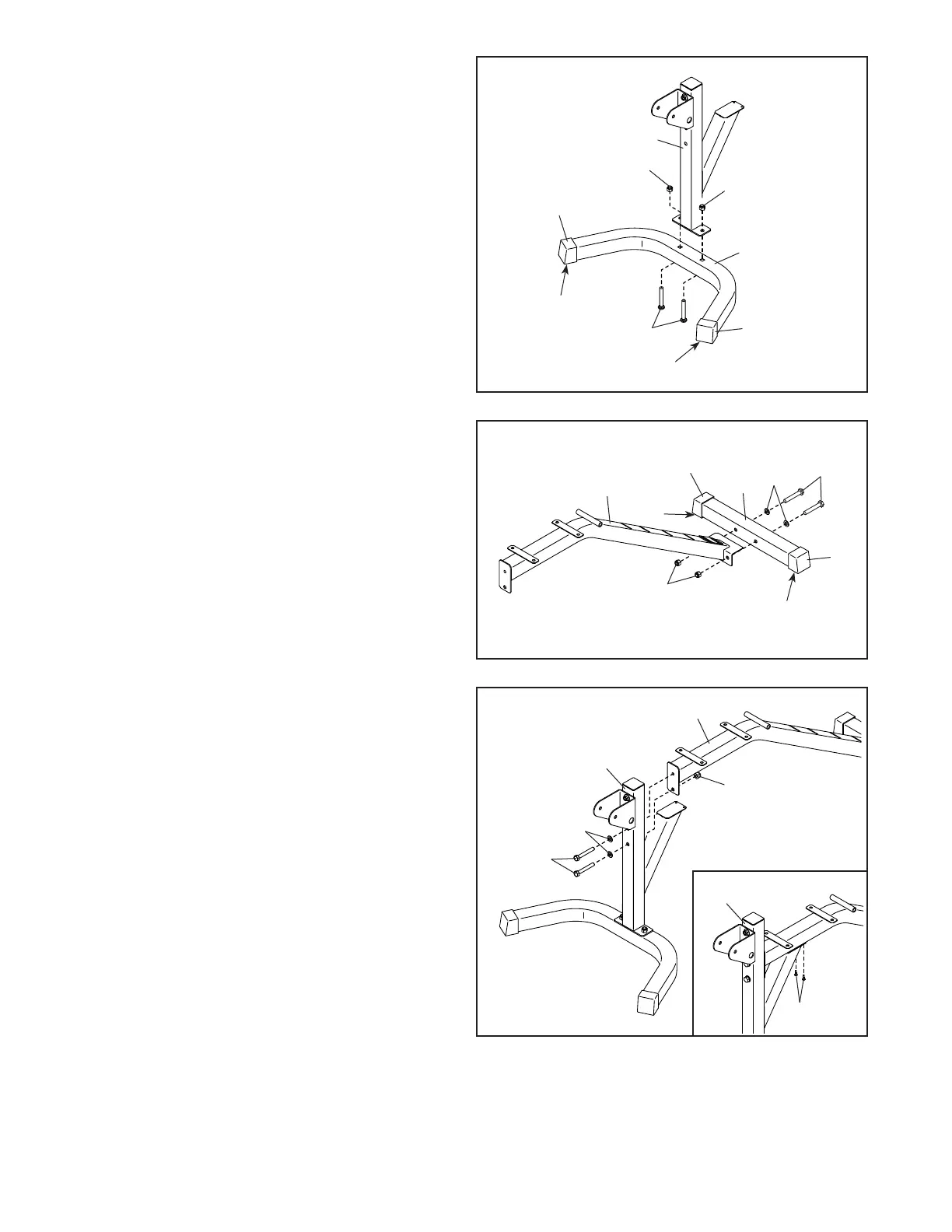
6. Orient the Rear Stabilizer (24) so that the widest
sides (B) of the 50mm Square Outer Caps (46)
touch the floor.
Attach the Rear Stabilizer (24) to the Frame
(22) with two M10 x 70mm Bolts (29), two M10
Washers (19), and two M10 Locknuts (17); do
not tighten the Locknuts yet.
6
7
7. Attach the Front Leg (25) to the Frame (22) with
two M10 x 70mm Bolts (29), two M10 Washers
(19), and an M10 Locknut (17); do not tighten
the Bolts or the Locknut yet.
See the inset drawing. Finish attaching the
Front Leg (25) with two M4 x 19mm Screws (18);
start both Screws, and then tighten them.
Then, tighten the two M10 x 70mm Bolts (29)
and the M10 Locknut (17).
See step 5–6. Tighten the M10 Locknuts (17).
22
25
17
19
29
46
46
22
17
24
B
B
18
25
29
19