Pro1 Technologies
P.O. Box 3377
Springeld, MO 65808-3377
Toll Free : 888-776-1427
Web: www.pro1iaq.com
Hours of Operation: M-F 9AM - 6PM EST
Thermostat Application Guide
Description
Gas or Oil Heat
Electric Furnace
Heat Pump (No Aux. or Emergency Heat)
Heat Pump (With Aux. or Emergency Heat)
Multi-Stage Systems
Heat Only Systems
Cool Only Systems
Millivolt
Yes
Yes
Yes
No
No
Yes
Yes
No
Table of Contents
Specications
Installation Tips
Thermostat Quick Reference
Subbase Installation
Wiring
Technician Setup
WIFI Setup
Page
2
3
4
5-6
7-8
1
Power Type
Hardwire (24V Common Wire)
Rev. 1932
Specications
The display range of temperature .............................. 41˚F to 95˚F (5˚C to 35˚C)
The control range of temperature............................... 44˚F to 90˚F (7˚C to 32˚C)
Load rating............................................................................1 amp per terminal, 1.5 amp
maximum all terminals combined
Display Accuracy................................................................. ± 1˚F
Swing (cycle rate or dierential) .................................. Heating is adjustable from 0.2˚ to 2.0˚
Cooling is adjustable from 0.2˚ to 2.0˚
Power source .......................................................................18 to 30 VAC, NEC Class II, 50/60 Hz
for hardwire. 500 mA
Operating ambient ........................................................... 32˚F to +105˚F (0˚C to +41˚C)
Operating humidity .......................................................... 90% non-condensing maximum
Dimensions of thermostat .............................................. 4.7”W x 4.4”H x 0.8”D
Una version en espanol de este
manual se puede descargar en la
pagina web de la compania.
A trained, experienced
technician must install this product.
Carefully read these
instructions. You could damage this
product or cause a
hazardous condition if you fail to
follow these instructions.
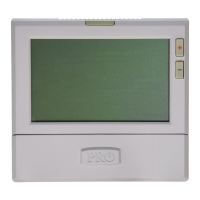
T701i
Product Installation Guide Installation Tips
Wall Installation
The thermostat should be installed approximately 4 to 5 feet above the oor.
Select an area with average temperature and good air circulation. Pick an
installation location that is easy for the user to access. The temperature of the
location should be representative of the building.
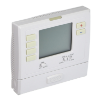
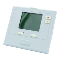
Removing The Private Label Badge
Gently slide a screwdriver into the
bottom edge of the badge. Gently
turn the screwdriver counter
clockwise. The badge is held on by
a magnet in the well of the battery
door. The badge should pry o easily.
DO NOT USE FORCE.
All of our thermostats use the same
universal magnetic badge. Visit the
company website to learn more about
our free private label program.
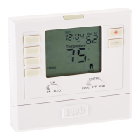
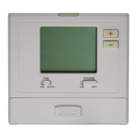
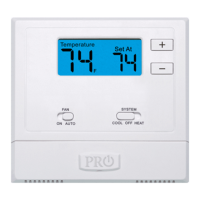
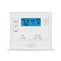
Glow in the dark light button
Fan button
System button
Temperature setpoint buttons
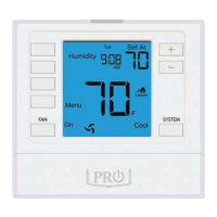
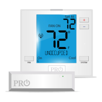
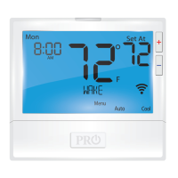
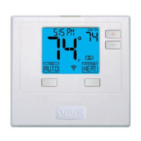
LCD
Displays the user
selectable setpoint
temperature.
Indicates mode of
system running.
(Flashing indicates
5 min compressor
delay).
WIFI Connection
lndicator
Bottom right text eld used
in programming and hold
functions. Will also show
current system setting.
WIFI signal
strength
Fan
Indicator
Bottom left text eld used in
programming and hold
functions. Will also show
current fan setting.
Indicates the
current room
temperature.
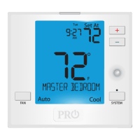
Top text eld used in
programming, will
also show time of day
when a schedule pro-
gram is being used.
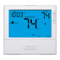
Thermostat Quick Reference
Vertical Mount
Horizontal Mount
For horizontal mount put one
screw on the left and one screw
on the right.
All of our products are mercury free.
However, if the product you are replacing
contains mercury, dispose of it properly.
Your local waste management authority
can give you instructions on recycling and
proper disposal.
Mercury Notice
Failure to disconnect the power before
beginning to install this product can cause
electrical shock or equipment damage.
Electrical Hazard
Subbase Installation
For vertical mount put one
screw on the top and one screw
on the bottom.
Mount Thermostat
Align the 4 tabs on the subbase
with corresponding slots on the
back of the thermostat, then push
gently until the thermostat snaps
in place.
NOTE: To ensure a solid t between
the thermostat and subbase:
1. Mount subbase on a at wall.
2. Use provided screws.
3. Ensure drywall anchors are ush with wall.
4. Push wires into wall.
WIFI
Frequency Range............2.4 Ghz ISM radio band
WIFI Module...............................Supporting 802.11
B/G/N Standards
9
Do not install
thermostat in locations:
• Close to hot or cold air ducts
• That are in direct sunlight
• With an outside wall behind the
thermostat
• In areas that do not require
conditioning
• Where there are dead spots or
drafts (in corners or behind doors)
• Where there might be concealed
chimneys or pipes
Magnet in door
Use the bevel on lower ridge
U.S. Registered Trademark. Patents pending
Copyright 2019 All Rights Reserved.