Em.Heat
AutoCool
AutoIAQ
Set At
On LHM
Tech Set
Set Sched
Next
Run Sched
Set Time
Hold
Done
Menu
Prev
HOLD
STAGES
1+2+3+4
COOL ON
HEAT ON
FAN ON
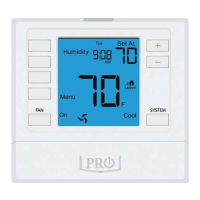
Humidity
Zone
Yes
Humidity %
Outdoor AMPM
SunMonTue
WedThuFriSat
REMOTE
WAKELEAVE
RETURN
SLEEP
5
6
9
10
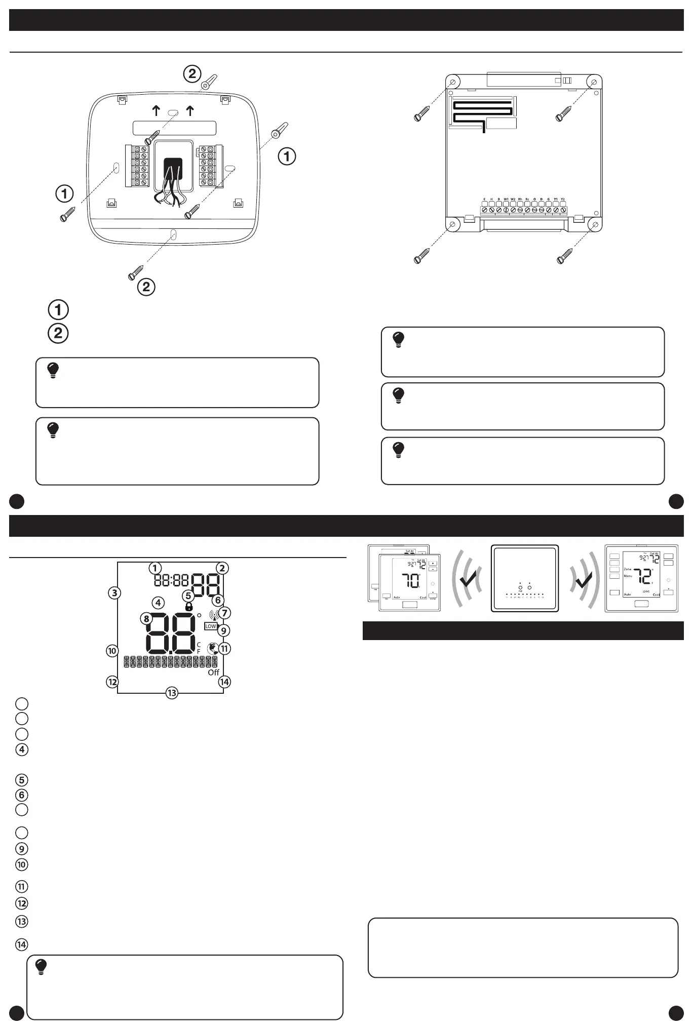
Installation Tips
Installation Tips
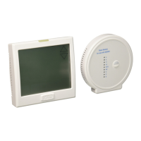
Wireless Communication Setup
Follow these steps to setup the PROsync Wireless System
1. Choose the equipment module location.
2. Remove the front cover and attach the equipment module to the wall.
3. Wire the equipment module to the air handler.
4. Snap the cover back on. The C terminal light should be illuminated
indicating the equipment module is powered.
5. Install batteries in the main thermostat and ensure it is communicating
with the equipment module. Any changes to the main thermostat
that create a call will now be displayed at the equipment module
in the LEDs associated with the terminals.
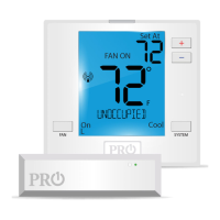
6. Choose the install location for the T755WHO. In the tech settings, check
the “Signal Strength” tech setting and ensure the value is greater than zero.
7. Remove the subbase and attach it to the wall using screws and
anchors in the box.
8. If you want to hardwire the thermostat, connect the R and C wires.
9. Snap the thermostat onto the subbase. Make sure the connection
is secure and the display is illuminated.
10. Add any additional remote sensors as desired.
Note.
Each time a message goes back and forth between the remote
thermostat and the equipment module, the light on the equipment
module will blink blue twice, and the antenna icon on the remote will
blink twice.
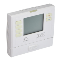
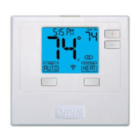
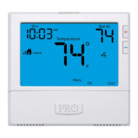
Getting to know your thermostat
The low battery indicator is displayed when the AA battery power is low. Replace the
batteries when the indicator appears. If the system is in the low battery state for an
extended period, the system will operate with reduced temperature control. If battery power
is lost, the system will cease operation even if the equipment module is still connected.
Important
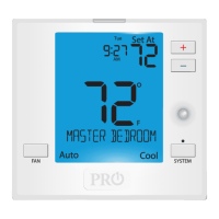
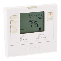
Indicates the current room temperature
Time and day of the week
Setpoint: Displays the selected setpoint temperature.
Hold is displayed when the thermostat program is permanently overridden.
System Operation Indicators:
The COOL ON, HEAT ON, or FAN ON will display when the COOL, HEAT, or
FAN is on. The compressor delay feature is active if these are ashing.
Low Battery Indicator: Replace batteries when this indicator is shown.
Menu Options: Shows dierent options.
Program Time Periods: This thermostat has 4 programmable time periods
per day.
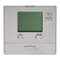
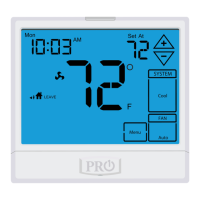
System: Indicates current mode of operation.
Stages: 1 will appear in the display when the rst stage of heat or cool is on, +2
will appear for the second stage, +3 for third stage and +4 for fourth stage.
1
2
3
7
8
Globe: Globe is displayed if an energy ecient temperature has been selected.
Thermostat Quick Reference
Keypad Lockout: Indicates keypad lockout state is “Locked”.
Radio Antenna: This icon blinks when the thermostat receives a message
from the equipment module.
Vertical Mount
Horizontal Mount
For horizontal mount put one screw on
the left and one screw on the right.
All of our products are mercury free. However, if the product you are
replacing contains mercury, dispose of it properly. Your local waste
management authority can give you instructions on recycling and
proper disposal.
Mercury Notice
Failure to disconnect the power before beginning to install this product
can cause electrical shock or equipment damage.
Installation Tip: Electrical Hazard
For vertical mount put one screw on
the top and one screw on the bottom.
Thermostat Subbase Installation
Equipment Module Subbase Installation
For the equipment module mount 4 screws in each outer hole.
To connect the equipment module to the master thermostat, refer to
the directions on page 11 of this manual.
Note:
Wire the equipment module’s subbase the same way you would wire a
hardwired thermostat subase.
Wiring Note
The base module must be hardwired (C and R terminals connected to
24V power.)
Note:
Fan Mode: Indicates current air handler fan mode of operation.