20 © 2016 Proceq SA
3.3.2.4 Test Conditions
To ensure proper hardness readings, the following conditions must be
fulfilled. If one or more conditions are not met, the result may be signifi-
cantly false.
Probe setup 50 N
probe
with
clamp
50 N probe
with round
standard
foot (ø =
42 mm)
50 N
probe
with
tripod
50 N probe
with spe-
cial feet
Minimum test
piece thickness
1 mm at ~20 HB
130 μm at ~70 HRC
Maximum test
piece thickness
40 mm N/A
Test piece surface
condition
recommended mean surface roughness
R
a
< 2 μm to minimize data scatter
Surface
curvature
foot to be
used for
plane
surfaces
very
small cur-
vatures
accepta-
ble
18 – 70 mm
radius of
curvature or
70 mm – ∞
Maximum test
piece hardness
70 HRC
Minimum spacing
three times the diameter of a test indentation
Table 3: Portable Rockwell Test Piece Requirements
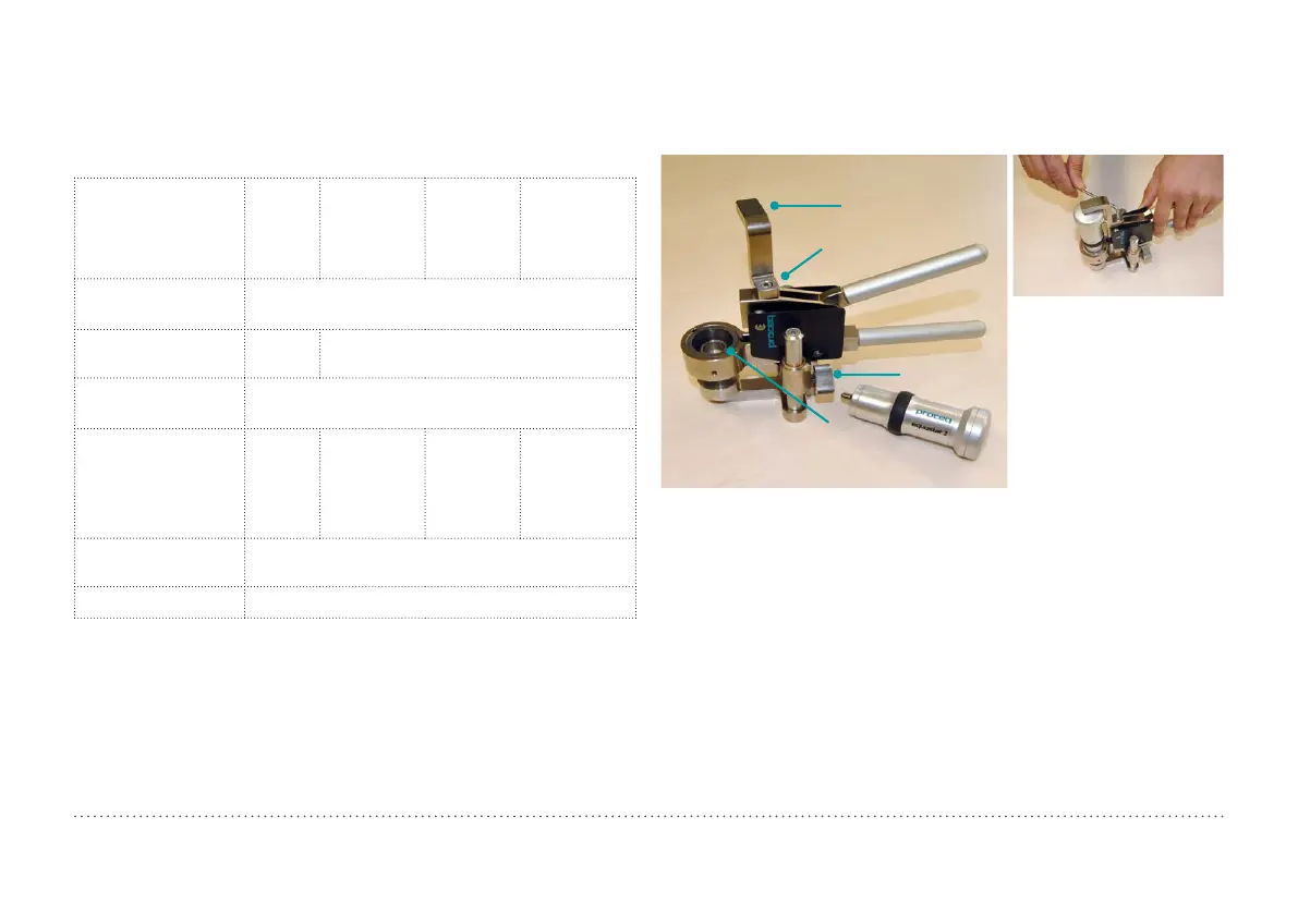
3.3.2.5 Installing the Measuring Clamp
The clamp is designed to facilitate the hardness testing of very thin or
small samples.
Cantilever
Cantilever screw
Knurled screw
Probe holder
Figure 16: Portable Rockwell Clamp
• Use the 3 mm Allen key setup tool to release the cantilever. Turn it by 90°.
• Take the probe and remove the foot. The diamond indenter remains
mounted.
• Screw the probe into the probe holder of the clamp clockwise (hand-tight).
• Turn the cantilever so its tip is centred over the probe; tighten the can-
tilever screw securely using the 3 mm Allen key setup tool.
• The recommended clearance between the bottom of the probe holder
and the sample surface should be between 2 and 5 mm. Adjust the
height with the two knurled screws.