M-34-01
Revision - Date: 01 - 04/23/08
DQ15D Manual
10
Calibration
Calibration Procedure
1 Turn OFF all power.
2 Remove rear cover.
3 Ensure the 2 wire, 1000 ohm
RTD sensor is connected across
terminals #1 AND #2 of the
terminal block before beginning.
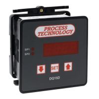
4 Remove RTD sensor.
5 Install the precision resistors in
place of the RTD, as shown.
7 Carefully restore power to the
control, taking precautions not to
make contact with any exposed
voltage sources.
8 Press and hold and
simultaneously for approximately 6
seconds. The display will indicate
AC.0
. While the
0
is flashing, use
to change this to
22
. Press
SET
. The
control screen displays
CAL1
.
9 Press and hold
SET
for 1 second.
HoLd
displays on the screen.
Wait for
CAL2
to display.
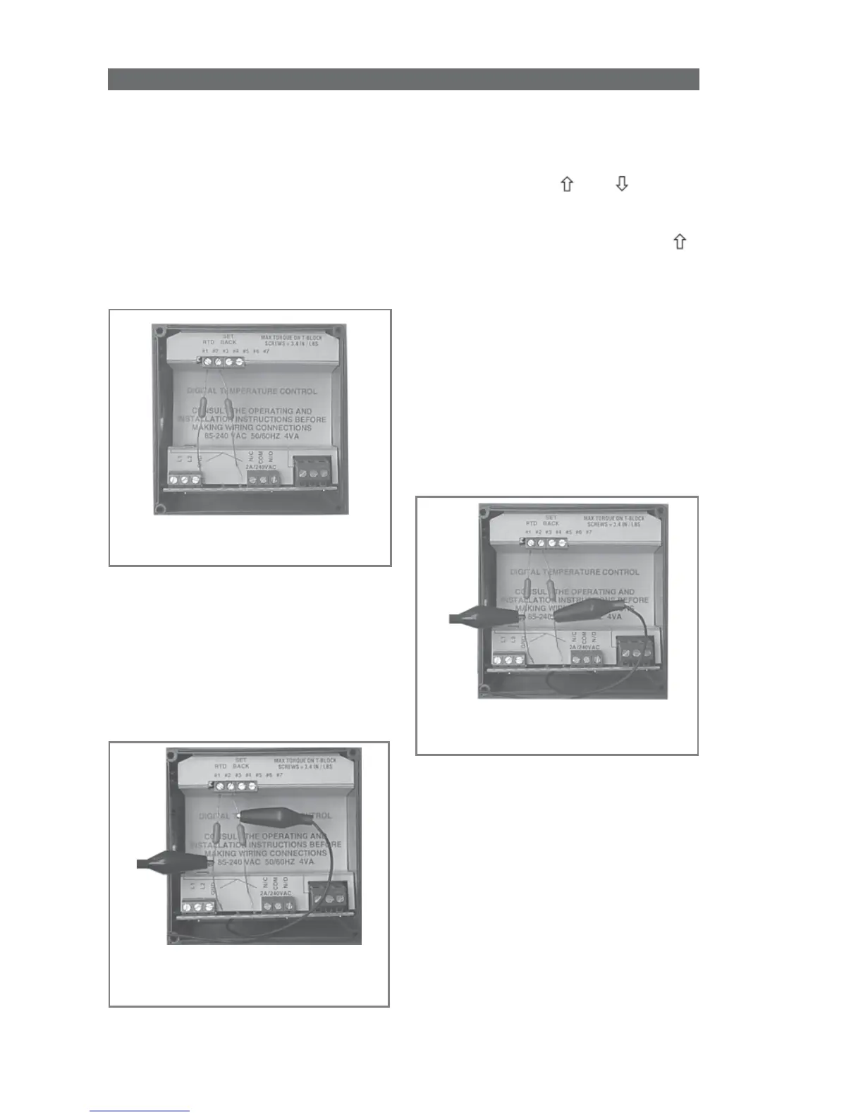
10 Proceed with caution to avoid
SHOCK hazard. Remove and
relocate one end of the jumper
cable to the loose end of the
second precision resistor for the
second resistance value (i.e. 2000
ohms), as shown.
RTD Calibration - Precision Resistors
in Place of the RTD Sensor
RTD Calibration - Jumper Cable in
Place for Second Resistor
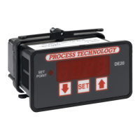
6 Install the jumper cable between
the loose end of one resistor and the
fixed end of the other resistor to
establish an input value of a single
resistor (i.e. 1000 ohms), as shown.
RTD Calibration - Jumper Cable in
Place for First Resistor
11 Press and hold
SET
for 1 second.
The screen displays
HoLd
. WAIT
for the display to reset. After
resetting, the connected precision
resistors’ approximate temperature
value should display (i.e. 511° F or
266° C).
12 Turn OFF power and remove
the precision resistors. Reinstall the
RTD sensor and the rear cover of
the controller. Return the calibrated
control to service.