4 After the option has been deter-
mined, press
SET
once more to lock
the new value into memory.
5 After completing all changes to the
configuration of the control, the new
configuration must be saved. To save
the new value, press
and simulta-
neously. This will cause the control to
store the new values internally and
then reset the unit.
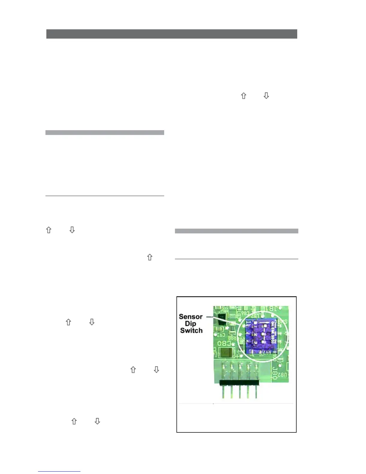
Sensor DIP Switch
When using the sensor 5416 or 5447
boards, an on-board DIP switch
must also be configured.
Sw1 Sw2 Sw3 Type
OFF OFF OFF 1000 ohm RTD
ON OFF OFF 100 ohm RTD
OFF ON OFF voltage
OFF OFF ON current
OFF OFF OFF frequency
Note: Switching off power to the unit
before saving the new configuration will
cause all changes to be lost.
RTD Error Messages
If the screen displays one of the
following messages, the control
relay de-energized due to an RTD
condition.
HHH A thermocouple or RTD
sensor is improperly connected, or
the control read an open circuit.
UUU The RTD sensor shorted.
Note: Thermocouple shorts cause a
new junction/measurement point to be
created. This will lead to false readings
and dangerous operating conditions.
Shorted thermocouples will not result
in an error condition. Instead, incorrect
readings will be displayed.
Configuration (Set-up)
1 To configure the DQ15D, press
and simultaneously and hold
for approximately 6 seconds. The
screen displays
AC.0
.
2 While the
0
is flashing, use to
change this to
11
. Press
SET
. The
control will be in the configuration
mode. While in this mode, the
screen displays the values of
various configuration settings. The
first setting to display is the
U1
setting. See setting summary. By
using
and keys, it is possible
to scroll through the list of settings
to those needing modification.
Adjust Configuration Setting
1 To adjust a setting while in the
Configuration Mode, use
and
to bring the particular setting into
the view on the screen.
2 Press
SET
to change the value of
the setting. Once
SET
has been
released, the display will flash.
3 Use and to scroll through
the options for the selected setting.