3 Wire RTD
Optional PCN 5447 or 5416 board
needed. This board will accept 2
wire RTDs as well. RTD devices
are precision resistors whose
resistance value varies with
temperature. The connection of a
third wire eliminates the natural
resistance of the lead wires to
improve sensor accuracy. The
DQ15D control measures the RTD
resistance (and the third wire
resistance) and compares that
measurement with a standard set
of values stored in the memory.
You can restore, update or verify that
the standard set of values is correct.
Note: For a 1000 ohm sensor, the DIP
switches should be OFF, OFF, OFF.
For 100 ohm, ensure the DIP switches
are ON, OFF, OFF. See Dip Switch
Settings in Configuration (Setup).
Equipment needed
• Two precision resistors (tolerance
+/- 0.1% or better) with a fixed
value equal to the RTD nominal
value (i.e. 1000 or 100 ohms).
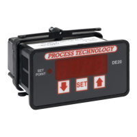
• A suitable jumper cable to
facilitate changing input
resistance.
• A short piece of jumper wire
(simulates third wire).
Warning!
Calibration procedures require the
removal of the rear cover of the
control. It also requires that power is
ON, exposing the technician to
potentially lethal voltages. Always
Exercise EXTREME CARE and wear
tested electrician’s gloves when
power is on.
Calibration Procedure
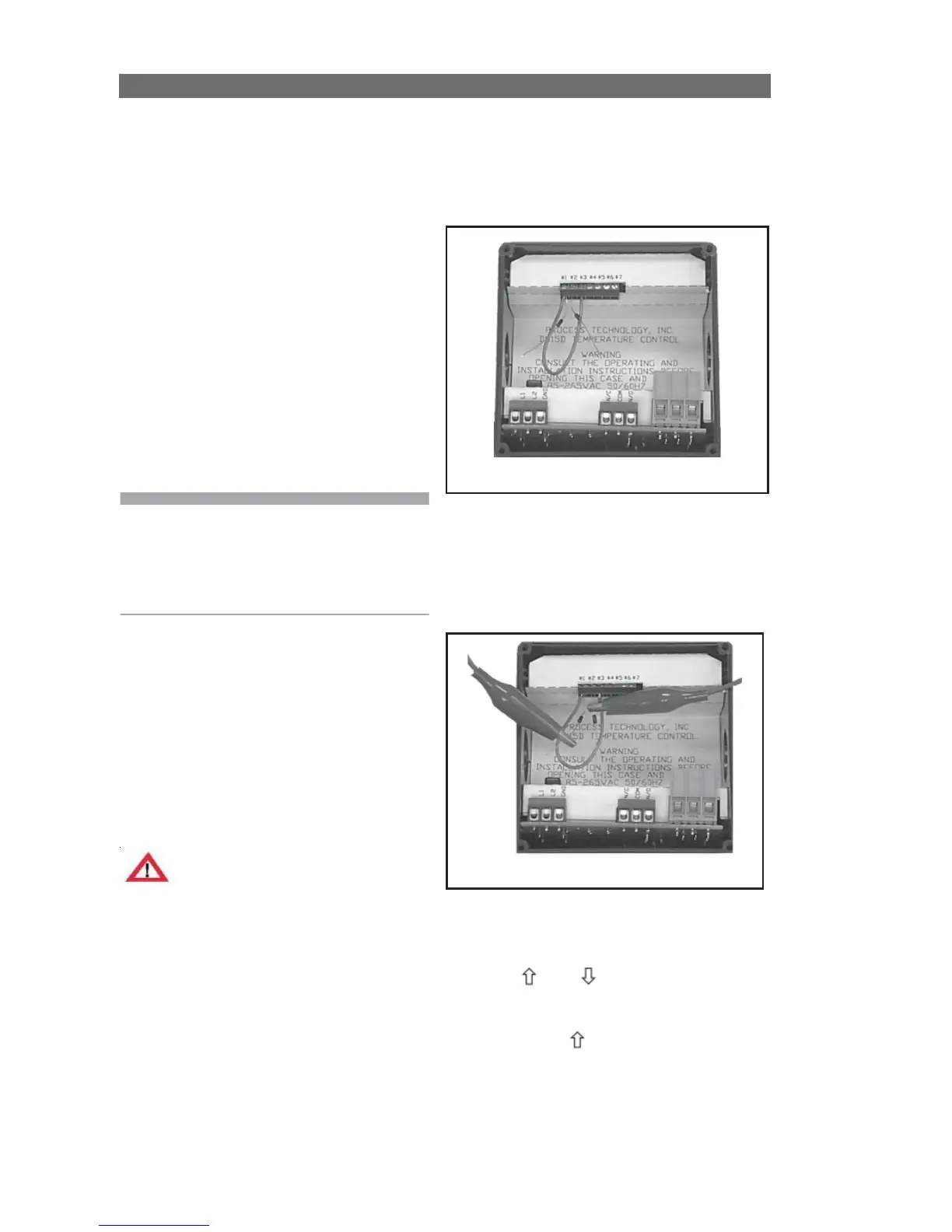
1 Turn OFF all power.
2 Remove rear cover.
3 Remove RTD sensor.
7 Carefully restore power to the
controller. Do not come in contact
with any exposed voltage.
8 Press and simultaneously
and hold for approximately 6 sec.
The screen displays
AC.0
. While the
0
is flashing, use to change this to
22
. Press
SET
.
CAL1
displays.
9 Press and hold
SET
for one sec.
The screen displays
Hold
. Wait for the
message to change to
CAL2
.