Calibration
This section includes calibration
procedures for 2 & 3 wire RTDs,
Resistance, Voltage, Current Input,
Frequency, and Thermocouples.
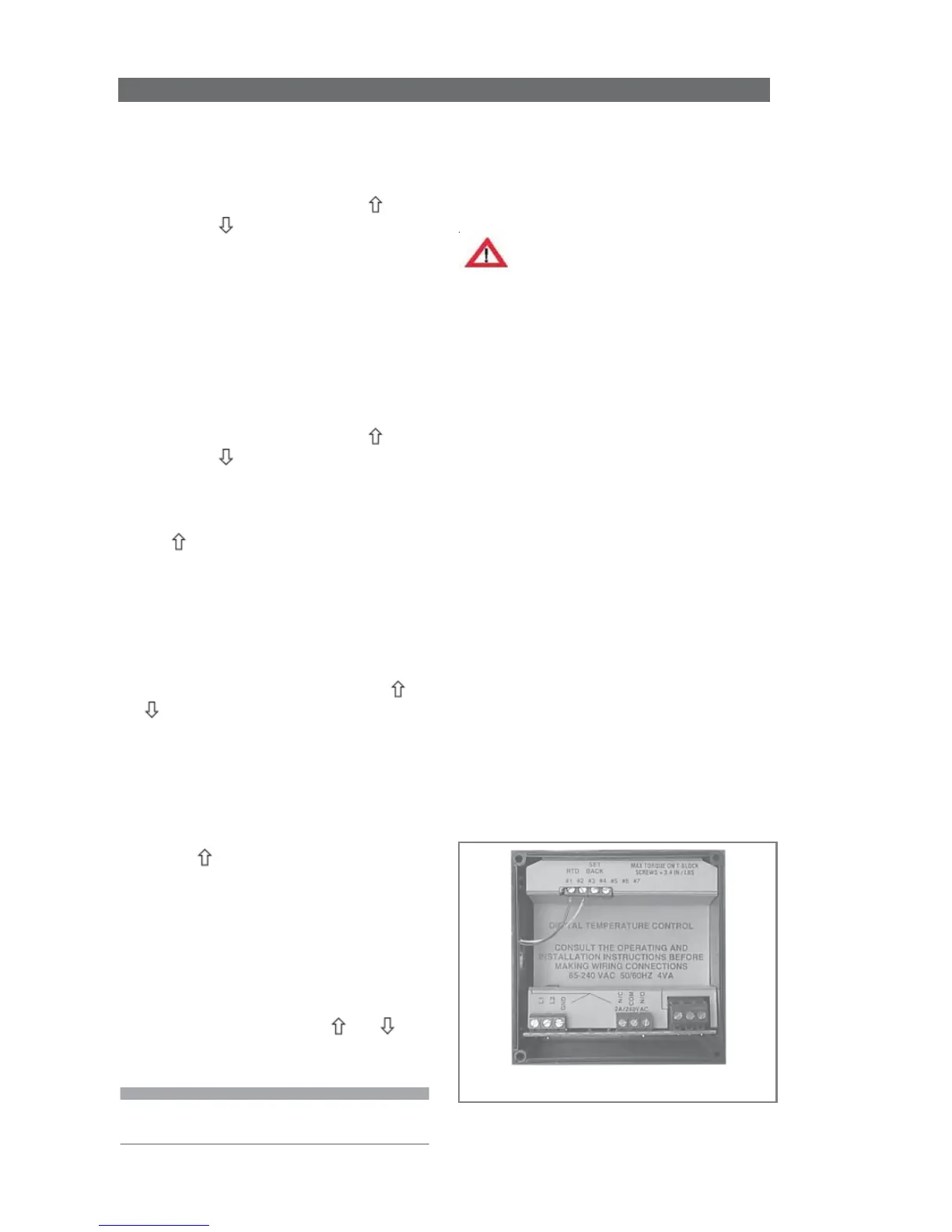
Warning!
Calibration procedures require the
removal of the rear cover of the
control. It also requires that power is
ON, exposing the technician to
potentially lethal voltages. Always
Exercise EXTREME CARE and wear
tested electrician’s gloves when power
is on.
2 Wire RTD
RTD devices are precision resistors
whose resistance value varies with
temperature. DQ15D measures RTD
resistance and compares that value
with a standard set of values stored
in memory. You can restore, update
or verify that this standard set of
values is correct.
Equipment needed
• Two precision resistors (tolerance
+/- 0.1% or better) with a fixed
value equal to the RTD nominal
value (i.e. 1000 ohms).
• A suitable jumper cable to
facilitate changing input
resistance.
P-Power Save Set Point
1 To turn on the Power-Save
feature, do one of the following
tasks, never do both:
• either press all three keys (
,
SET
, and ) simultaneously, or
• install an external switch to close
contacts #3 and #4 on the rear
terminal strip.
When the control is operating in
Power-Save mode, the display will
alternately change between the
process value and three dashes ---.
2 Return to normal
SP1
operation
with one of the following tasks:
• either press all three keys (
,
SET
, and ) simultaneously, or
• switch OFF the remote switch
wired to terminals #3 and #4.
3 To view the P
SET
POINT value,
press
once and release. The
control will display the letter P and
a decimal point followed by the
numeric
P
SET
POINT value.
4 To change the Set Point value,
press
SET
while the P
SET
POINT
value displays (value will flash).
5 Once the value flashes, press
or to change the value.
6 Press
SET
once to lock the new
value into memory.
Alarm Set Point
1
Enable the Alarm feature. See
Configuration (Setup), F3 Alarm
On/Off Switch for instructions.
2 Press twice and release. The
letter
A, followed by a decimal point
and the Alarm Set Point value
displays. (After a few seconds the
screen returns to normal.)
3 To change the ALARM SET POINT,
press
SET
while the alarm Set Point
value still displays (value will flash).
4 When it flashes, use or to
change the value, and press
SET
to
lock the new value into memory.
Note: Alarm Set Point is not a safety
device.