M-34-01
Revision - Date: 01 - 04/23/08
DQ15D Manual
13
Calibration
Verify Standard Values
To restore, update or merely verify
that this standard set of values is
correct, do the following:
• Make sure that the DIP switch
settings are OFF, ON, OFF. See
Dip Switch Settings in
Configuration (Setup).
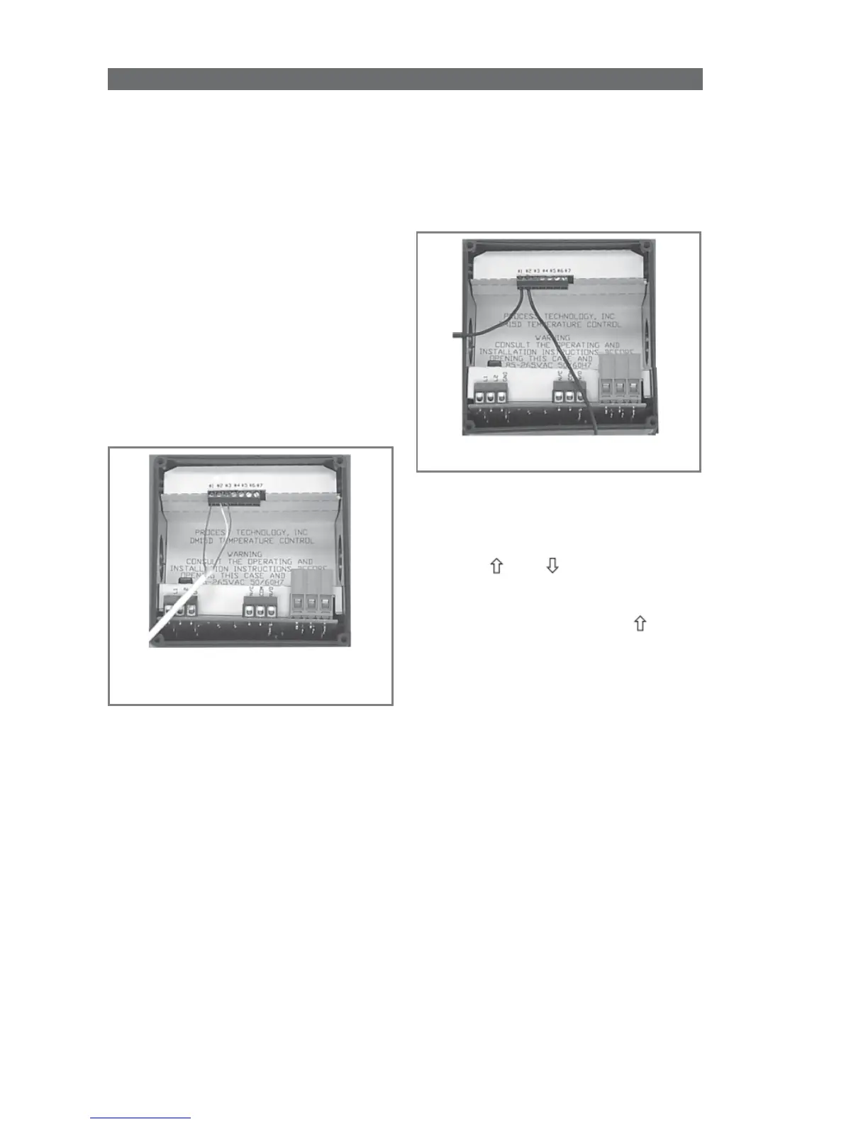
• The voltage signal must be
connected across terminals #1
and #2 of the Adder Board
(PCN 5416 or 5447). Terminal
#2 is common (negative), and
terminal #1 is the signal
connection (positive).
• Always observe polarity.
Calibration Procedure
1 Turn OFF all power.
2 Remove rear cover.
3 Remove voltage input wiring.
4 Install a voltage calibrator or
power supply to terminals 1 and 2.
Verify Standard Set of Values for
Voltage Signal
5 CAREFULLY restore power to
the controller, ensuring that you do
not come in contact with any
exposed voltage.
6 Press and simultaneously
and hold for approximately 6
seconds. The screen displays
AC.0
.
While the
0
is flashing, use to
change this to
22
. Press
SET
. The
control screen displays
CAL1
.
7 Adjust power supply to 1.0V.
8 Press and hold
SET
for one
second. The screen displays
Hold
.
Wait for display to change to
CAL2
.
9 Adjust calibrator to 10.0V.
10 Press and hold
SET
for one
second. The screen displays
Hold
.
Wait for display to reset and display
10.0.
11 Turn OFF power to the control
and remove the calibrator. Reinstall
the voltage input and the rear cover
of the control. Return the cali-
brated control to service.