10
Installing Blower Accessory
BLOWER ACCESSORY MODEL PF06-YJLF-F FOR QL300TYLA. QN300TYLA
NFHTX186 FOR QL220TYLA. QN220TYLA
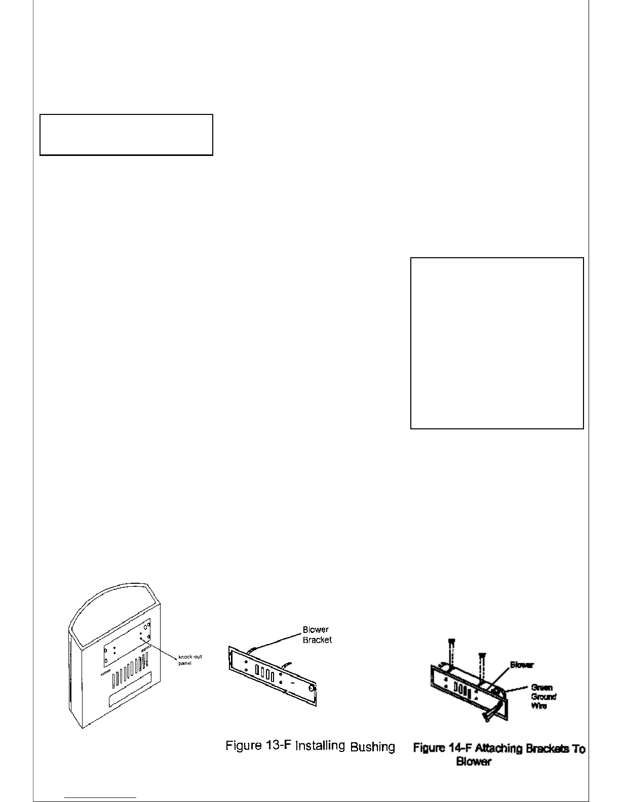
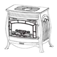
Figure 12-F -Removing
stove Knock-out panel
WARNING:
1. ELECTRICAL GROUND-
ING INSTRUCTIONS: This appliance is
equipped with a three-prong ground-
ing plug for your protection against
shock hazard and should be plugged
directly into a properly grounded
three-prong receptacle.
2. Do not let the wires touch the re-
flect panel of the firebox, let the wires
of the motor and green wire through
the hole of the Knock-out panel.
ACCESSORY PF06-YJLF-F OR
NFHTX186
Tool required: Philips screwdriver
1. From back of heater remove the
Knock-out center panel with two
brackets at the four sides with a
Philips head screwdriver (see
Figure12-F).
2. Attach the two brackets to blower
housing using four white screws
provided in blower kit (2 for each
bracket) (see Figure 14-F).
Tighten screws securely. Then
guide the green grounding wire
and downlead of motor through
the rubber capped hole.
3. Then guide the four strand wire
downlead through the jacket
hole, connect the two yellow
leads and the temperature con-
trol switch on the temperature
controlled bracket together. Se-
cure the temperature controlled
bracket on the reflect panel of fire-
box using two self-tapping
screws. (See Figure 15-F).
4. Using the screws previously
removed, mount blower assem-
bly to stove by reattaching the
Knock-out center panel to rear
panel. Draw the four strand cable
backward so as to expose the
three black, green, white lines on
the four strand cable at the back of
rear panel. Be sure not to drop the
temperature cotrolled wire off the
reflect panel. Connect the green
grounding means wire and four
strand cable together, connect the
two black motor downleads re-
spectively and remaining two black
and white wires together by the
same means (see Figure 15-F).
(Note: the three wires must be
connected at the rear panel)
5. Use the thread that bind the electri-
cal wire previously to collect and
pack the connection wire outside
the cable.
6. Use screwdriver to loosen the
three self-tapping screws at the left
upper part on the rear panel. (See
Figure 16-F).
7. Then, secure the bracket of the
control housing tightly on the back
panel using self-tapping screws.
8. Using two black screws that are
provided in blower kit, mount
blower operation control housing
to the bracket (see Figure 16-F).
9. Check to make sure that the power
cord is completely clear of blower
wheel and there are no foreign ob-
jects in blower wheel.
NOTICE: Shut off gas heater dur-
ing the following blower
installation.
13. Using Auto/O/Man switch, turn
blower on and check for operation.
Turn on Auto/O/Man switch to the
desired position. In the Man posi-
tion it will remain constantly on. Auto
position will be controlled by the
thermostat on fan blower unit. To
stop the operation turn unit switch
to the O position.
14. All remaining parts from blower kit
may be discarded.
10. Peel off the backing paper and
stick the supplied wiring diagram
decal on the back panel as shown
in Figure 16-F.
11.Use screws provided in blower kit
to assemble the plate which as-
sembled with strain relief bush-
ing and power cord on the
knockout center panel.
12. Plug power cord into a convenient
3-prong grounded wall recep-
tacle near the stove.