v.080131 7
ENGLISH
ASSEMBLY
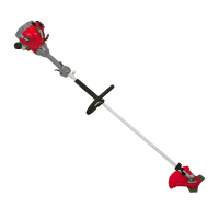
Attaching the “J” barrier handle
An auxiliary “J” barrier handle must be used for ensuring the best control and
maximizing operator safety when using a brush cutter. To attach the handle:
1. Place the machine upside-down (with the cutting head facing up) on a horizontal
surface.
2. Attach the cross tube clamp assembly (9-4, g.2) to the shaft housing (D, g.2)
using a 5mm hex key to tighten a clamp plate (9-3, g.2) over the shaft housing
with 2 hex socket head M6 x 16 bolts.
3. Turn the machine right side up.
4. Using a 5mm hex key turning 2 hex socket head M6 x 16 bolts, tighten the other
clamp plate over the J-handle onto the cross tube casting.
5. After assembly is complete, adjust the position of the handle for best balance
and comfort.
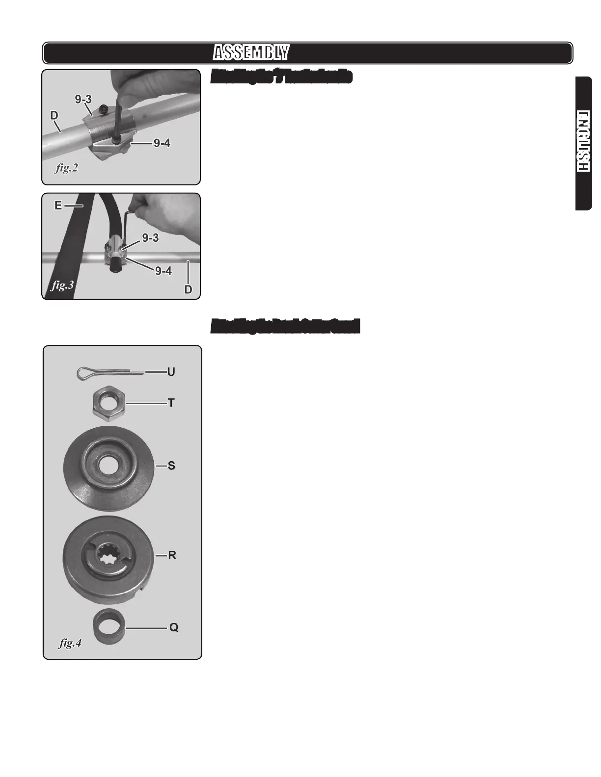
Attaching the Brush Cutter Guard
1. Remove the cutter attachment hardware (g.4) from the cutter head:
U. Nut retention cotter pin
T. M12 left-threaded hex nut- (turns clockwise to remove)
S. Blade retainer ange
R. Blade seat ange
Q. Spacer sleeve
Remove also from the gear head: 3 M6 x 15 torx/slot pan head screws