SYSTEM OWNER’S MANUAL
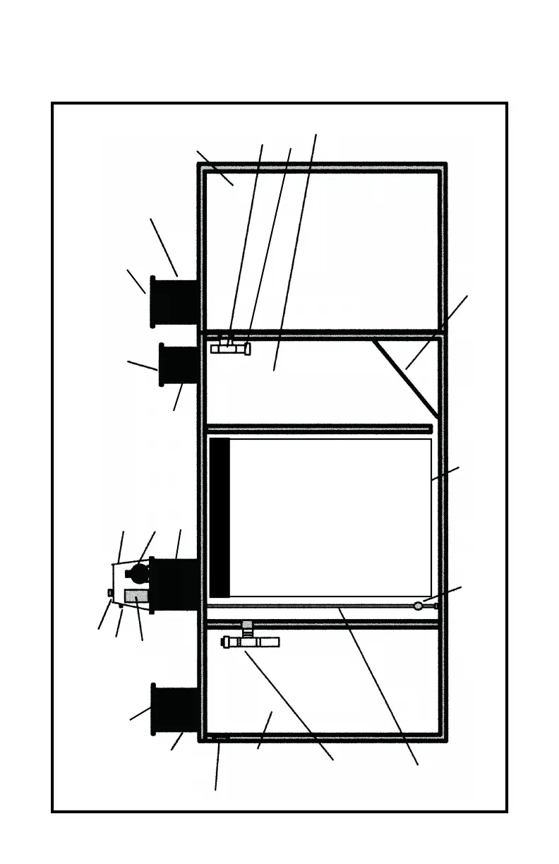
Inlet
20”
Pretreatment
Riser
Warning Light
447 Gal.
Pretreatment
4”
Pretreatment
Outlet
Baffle
748 Gal.
Aeration Chamber
Air Diffuser
45°
Slope
268 Gal.
Clarifier
Mute Switch
796 Gal.
Pump Tank
Clarifier Access
Aerator Cover
Aerator
Outlet
Baffle
#/4” PVC
Pipe
Control
Panel
7
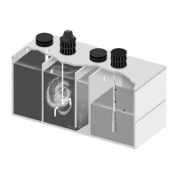
Pro Flo 600 SLPT System Diagram
Pretreatment
Access
20” Pump Tank
Riser
SPECIFICATIONS
Overall Length ....................... 179”(t) - 175”(b)
Overall Width ............................. 68”(t) - 64”(b)
Height without Risers ................................ 72”
Exterior Wall Thickness ............................... 3”
Interior Wall Thickness ................... 2”(t) - 3”(b)
Top Thickness ............................................ 5”
Bottom Thickness ....................................... 3”
Pretreatment Length ............. 32#/ 4”(t) - 30!/4”(b)
Aeration Length ......................... 53”(t) - 52”(b)
Clarifier Length .......................... 24”(t) - 23”(b)
Pump Tank ........................... 57!/4”(t) - 54#/ 4”(b)
Water Level .............................................. 55”
Air Diffuser ............................................... 27”
Bottom of Inlet to Bottom of Tank ............... 61”
Total Tank Weight (Empty) ............. 18,610* lbs
(t) = Top Dimension - (b) = Bottom Dimension
*Actual Scaled Weight
Drawing Not to Scale
All Gallonage Approximate
Pump Tank Access
Pro Flo 600 SLPT
Configurations may var y.
Pro Flo 600 SLPT GPD Unit
NOTE: If the wall between the Clarifier and Aeration
Chamber is a drop-in wall, the thickness shall be 2!/2”
Solids
Deflector
16” Clarifier
Riser
20” Aeration
Riser