SYSTEM OWNER’S MANUAL
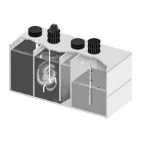
Inlet
Warning Light
503 Gal.
Pretreatment
Chamber
911 Gal.
Aeration Chamber
Air Diffuser
45°
Slope
317 Gal.
Clarifier
Mute Switch
Outlet
Clarifier
Access
Aerator
Cover
Aerator
Outlet
Baffle
#/4” PVC Pipe
Control
Panel
Pro Flo 800 PTSL
5
SPECIFICATIONS
10
Pro Flo 800 PTSL
5
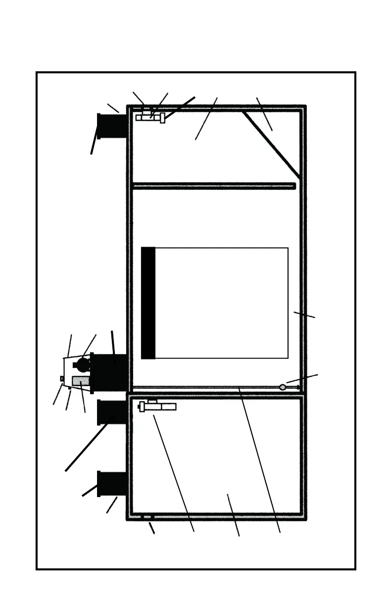
System Diagram
Overall Length .......... 140!/2”(t) - 136!/2”(b)
Overall Width ..................... 68”(t) - 64”(b)
Height without Risers ......................... 70”
Exterior Wall Thickness ........................ 3”
Inter ior Wall Thickness ........... 2”(t) - 3”(b)
Top Thickness ....................................... 4”
Bottom Thickness ................................. 3”
Pretreatment Length ..... 36#/4 ”(t) - 34!/4”(b)
Aeration Length ............64 !/2”(t) - 63!/2”(b)
Clar ifier Length ............. 29!/4”(t) - 26#/4”(b)
Water Level ......................................... 55”
Air Diffuser .......................................... 27”
Bottom of Inlet to Bottom of Tank .... 60!/2”
(t) = Top Dimension - (b) = Bottom Dimension
4”
Pretreatment
Outlet Baffle
Available only in limited areas
Pump Tank Sold Separately (Not Shown)
Drawing Not to Scale All Gallonage Approximate
Pretreatment Access
20” Pretreatment
Riser
16” Riser
Configurations may var y.
Pro Flo 800 PTSL
5
GPD Unit
NOTE: If the wall between the Clarifier and Aeration
Chamber is a drop-in wall, the thickness shall be 2!/2”
20” Aeration
Riser
16” Clarifier
Riser
Solids
Deflector