13
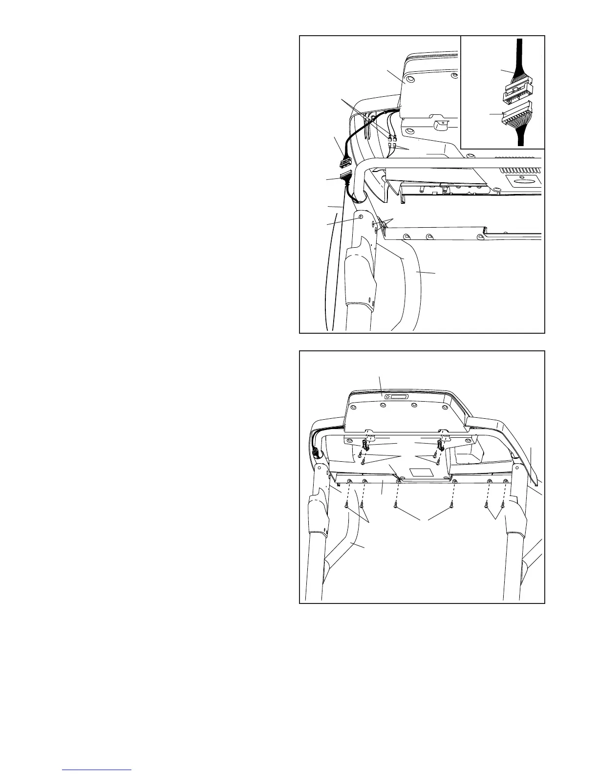
13. Set the console assembly on the Left and Right
Handrails (82, 83). Be careful not to pinch any
wires.
Attach the console assembly to the Crossbar
(107) with six #8 x 3/4" Screws (1). Start all six
Screws, and then tighten them.
Attach the two Console Clamps (105) to the
console assembly with four #8 x 1" Screws (53).
13
83
105
53
1
1
1
Console Assembly
82
107
12. Firmly tighten the four 5/16" x 1" Flat Head
Screws (3) and the two 5/16" x 1" Bolts (4) (only
one side is shown).
With the help of a second person, hold the con-
sole assembly near the Right Handrail (83) and
the Left Handrail (not shown).
Connect the Upright Wire (87) to the console
wire. See the inset drawing. The connectors
should slide together easily and snap into
place. If they do not, turn one connector and try
again. IF YOU DO NOT CONNECT THE CON-
NECTORS PROPERLY, THE CONSOLE MAY
BECOME DAMAGED WHEN YOU TURN ON
THE POWER. Then, remove the wire tie from
the Upright Wire.
Connect the two ground wires from the console
assembly to the two Console Ground Wires (52).
Console
Assembly
12
Console
Wire
Ground
Wire
Wire
Tie
83
87
4
3
Console
Wire
87
52
 Loading...