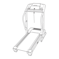
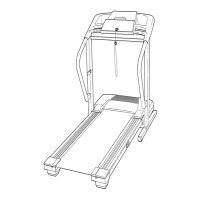
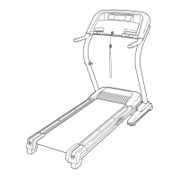
11
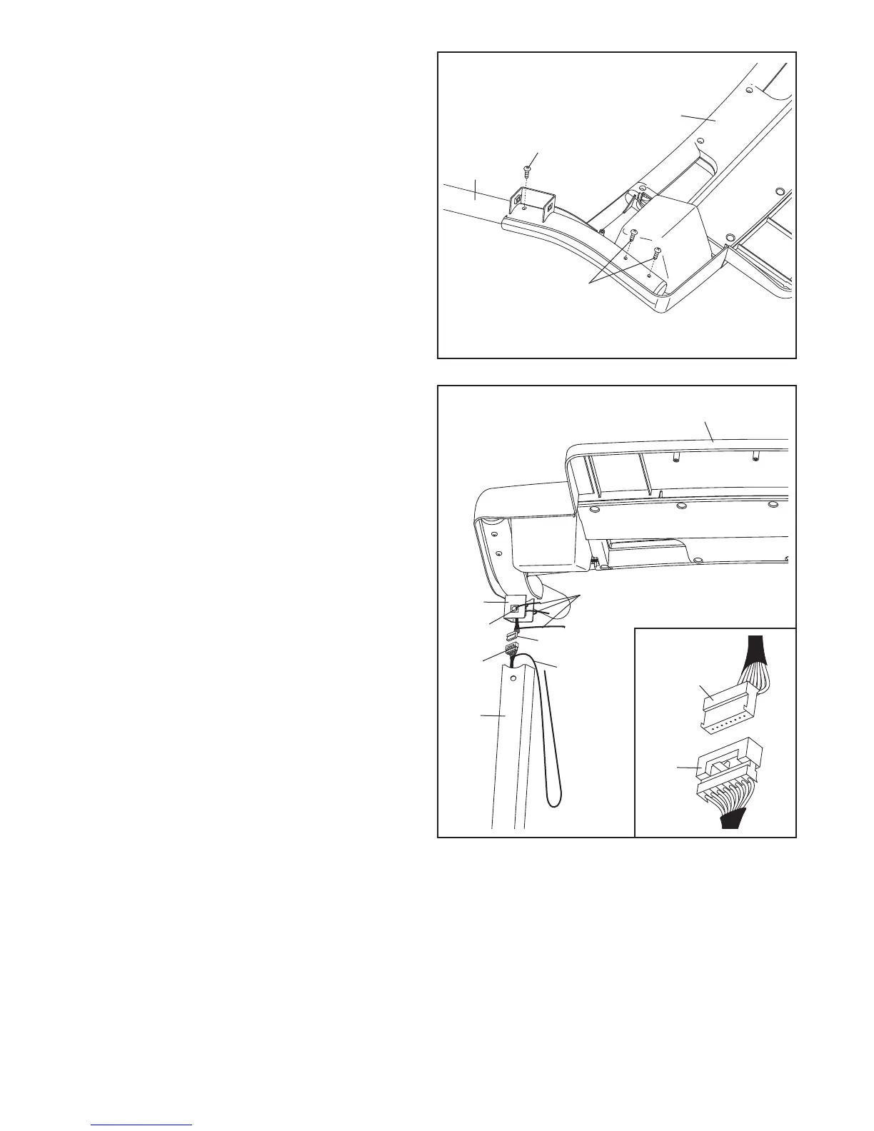
11. Attach the Left Handrail (89) to the console as-
sembly with three M4.2 X 19mm Screws (1).
S
tart all three Screws before tightening any
of them; do not overtighten the Screws.
12. Have a second person hold the console assem-
bly near the Right Upright (78). Cut the ties on
the Right Handrail (90) and Left Handrail (not
shown). If necessary, press the four Cage Nuts
(38) back into place.
Connect the Wire Harness (77) to the console
wire. See the inset drawing. The connectors
should slide together easily and snap into
place. If they do not, turn one connector and try
again. IF THE CONNECTORS ARE NOT CON-
NECTED PROPERLY, THE CONSOLE MAY
BE DAMAGED WHEN THE POWER IS
TURNED ON. Remove the wire ties from the
Wire Harness and the console wire. Then, insert
the connectors into the Right Upright (78).
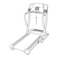
Set the console assembly on the Right Upright
(78) and the Left Upright (not shown). Make sure
that no wires are pinched.
78
Console Assembly
Console Wire
Wire Tie
Ties
77
12
77
90
Console
Wire
89
1
1
Console
Assembly
1
1
38
 Loading...